- 您現(xiàn)在的位置:買賣IC網(wǎng) > PDF目錄385354 > HC5523IM (HARRIS SEMICONDUCTOR) LSSGR/TR57 CO/Loop Carrier SLIC with Low Power Standby PDF資料下載
參數(shù)資料
| 型號: | HC5523IM |
| 廠商: | HARRIS SEMICONDUCTOR |
| 元件分類: | 模擬傳輸電路 |
| 英文描述: | LSSGR/TR57 CO/Loop Carrier SLIC with Low Power Standby |
| 中文描述: | TELECOM-SLIC, PQCC28 |
| 文件頁數(shù): | 10/18頁 |
| 文件大小: | 176K |
| 代理商: | HC5523IM |
65
Z
TR
is defined as:
Substituting in Equation 9 for V
TR
Substituting in Equation 12 for V
TX
Therefore
Equation 16 can now be used to match the SLIC’s
impedance to any known line impedance (Z
TR
).
Example:
Calculate Z
T
to make Z
TR
= 600
in series with 2.16
μ
F.
R
F
= 20
.
Z
T
= 560k
in series with 2.16nF
(AC) 2-Wire to 4-Wire Gain
The 2-wire to 4-wire gain is equal to V
TX
/ V
TR
From Equations 9 and 10 with V
RX
= 0
(AC) 4-Wire to 2-Wire Gain
The 4-wire to 2-wire gain is equal to V
TR
/V
RX
From Equations 9, 10 and 11 with E
G
= 0
For applications where the 2-wire impedance (Z
TR
,
Equation 15) is chosen to equal the line impedance (Z
L
), the
expression for A
4-2
simplifies to:
Z
RX
(AC) 4-Wire to 4-Wire Gain
The 4-wire to 4-wire gain is equal to V
TX
/V
RX
From Equations 9, 10 and 11 with E
G
= 0
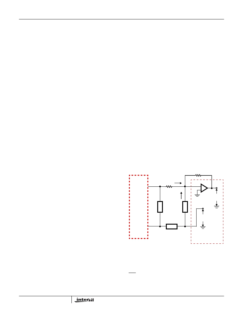
Transhybrid Circuit
The purpose of the transhybrid circuit is to remove the
receive signal (V
RX
) from the transmit signal (V
TX
), thereby
preventing an echo on the transmit side. This is
accomplished by using an external op amp (usually part of
the CODEC) and by the inversion of the signal from the
4-wire receive port (RSN) to the 4-wire transmit port (V
TX
).
Figure 17 shows the transhybrid circuit. The input signal will
be subtracted from the output signal if I
1
equals I
2
. Node
analysis yields the following equation:
The value of Z
B
is then
Where V
RX
/V
TX
equals 1/ A
4-4
Therefore
Example:
Given: R
TX
= 20k
, Z
RX
= 280k
, Z
T
= 562k
(standard
value), R
F
= 20
and Z = 600
The value of Z
B
= 18.7k
Supervisory Functions
The loop current, ground key and the ring trip detector
outputs are multiplexed to a single logic output pin called
DET. See Table 1 to determine the active detector for a given
logic input. For further discussion of the logic circuitry see
section titled “Digital Logic Inputs”.
Z
TR
V
M
-----------
=
(EQ. 13)
Z
TR
V
M
----------
2R
-----------------------
I
M
M
+
=
(EQ. 14)
Z
TR
Z
------------
2R
F
+
=
(EQ. 15)
Z
T
1000
Z
TR
2R
F
–
(
)
=
(EQ. 16)
Z
T
1000
600
j
ω
2.16
10
6
–
-----------------------------------------
2
20
–
+
=
A
2
4
–
V
TR
-----------
Z
1000
T
F
--------------------------+
=
=
(EQ. 17)
A
4
2
–
V
RX
-----------
Z
RX
-----------
–
Z
------------
2R
F
Z
L
+
+
--------------------------------------------
=
=
(EQ. 18)
A
4
2
–
-----------
–
1
2
--
=
(EQ. 19)
A
4
4
–
V
RX
-----------
Z
RX
-----------
–
Z
2R
+
------------
2R
F
Z
L
+
+
--------------------------------------------
=
=
(EQ. 20)
V
TX
-----------
V
B
-----------
+
0
=
(EQ. 21)
Z
B
R
–
TX
V
TX
-----------
=
(EQ. 22)
Z
B
R
TX
Z
T
-----------
Z
------------------+
------------
2R
F
F
Z
L
+
+
L
=
(EQ. 23)
HC5523
V
TX
RSN
R
TX
R
FB
CODEC/
FILTER
I
1
I
2
V
TX
Z
RX
Z
T
+
-
Z
B
V
RX
+
-
+
-
FIGURE 17. TRANSHYBRID CIRCUIT
HC5523
相關(guān)PDF資料 |
PDF描述 |
|---|---|
| HC5523IP | LSSGR/TR57 CO/Loop Carrier SLIC with Low Power Standby |
| HC5526CM | ITU CO/PABX SLIC with Low Power Standby |
| HC5526CP | ITU CO/PABX SLIC with Low Power Standby |
| HC5526IM | ITU CO/PABX SLIC with Low Power Standby |
| HC5526IP | ITU CO/PABX SLIC with Low Power Standby |
相關(guān)代理商/技術(shù)參數(shù) |
參數(shù)描述 |
|---|---|
| HC5523IMR4722 | 制造商:Rochester Electronics LLC 功能描述:- Bulk |
| HC5523IMX6176C | 制造商:Rochester Electronics LLC 功能描述:- Bulk |
| HC5523IP | 制造商:Rochester Electronics LLC 功能描述:- Bulk |
| HC-5524 | 制造商:INTERSIL 制造商全稱:Intersil Corporation 功能描述:EIA/ITU 24V PABX SLIC with 25mA Loop Feed |
| HC5526 | 制造商:INTERSIL 制造商全稱:Intersil Corporation 功能描述:ITU CO/PABX SLIC with Low Power Standby |
發(fā)布緊急采購,3分鐘左右您將得到回復(fù)。