- 您現在的位置:買賣IC網 > PDF目錄383055 > GS9000CCPJ (Electronic Theatre Controls, Inc.) Serial Digital Decoder PDF資料下載
參數資料
| 型號: | GS9000CCPJ |
| 廠商: | Electronic Theatre Controls, Inc. |
| 英文描述: | Serial Digital Decoder |
| 中文描述: | 串行數字解碼器 |
| 文件頁數: | 4/8頁 |
| 文件大小: | 106K |
| 代理商: | GS9000CCPJ |

4
522 - 49 - 01
G
SCE
V
DD
V
DD
SDI
SCI
BIAS
SDI
SCI
V
DD
V
DD
GS9000C PIN DESCRIPTIONS
PIN NO.
SYMBOL
TYPE
DESCRIPTION
15
SWC
Input
Sync Warning Control
. Analog input used to set the HSYNC Error Rate (HER). This is
accomplished by an external RC time constant connected to this pin.
16
PCLK
Output
Parallel Clock Output.
CMOS (TTL compatible) clock output where the rising edge of the clock is
located at the centre of the parallel data window within a given tolerance. See Fig. 7.
17
PD0
Output
Parallel Data Output - Bit 0 (LSB)
. CMOS (TTL compatible) descrambled parallel data output from
the serial to parallel convertor representing the least significant bit (LSB).
18
V
DD
Power Supply
. Most positive power supply connection.
19 - 25
PD1 - PD7
Outputs
Parallel Data Outputs - Bit 1 to Bit 7.
CMOS (TTL compatible) descrambled parallel data outputs from
the serial to parallel convertor representing data bit 1 through data bit 7.
26
V
SS
Power Supply.
Most negative power supply connection.
27
PD8
Output
Parallel Data Output.
CMOS (TTL compatible) descrambled parallel data output from the serial to
parallel convertor representing data bit 8.
28
PD9
Output
Parallel Data Output - Bit 9 (MSB).
CMOS (TTL compatible) descrambled data output from the serial
to parallel convertor representing the most significant bit (MSB).
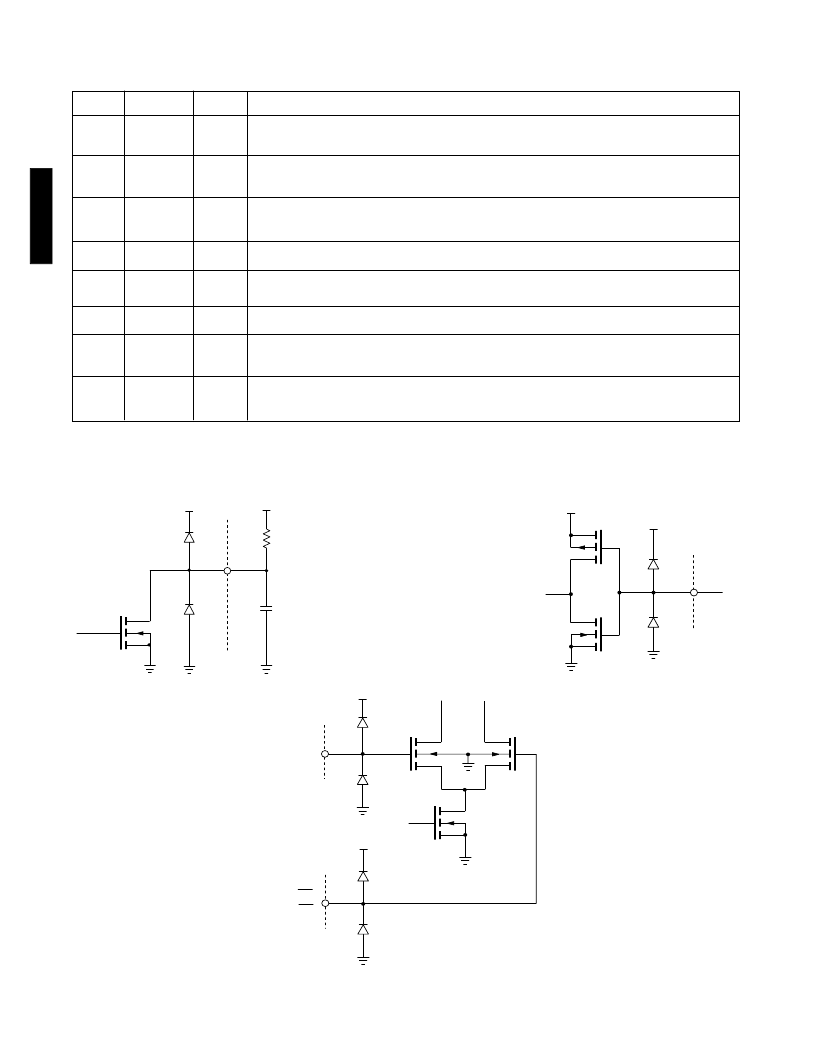
INPUT / OUTPUT CIRCUITS
Fig. 4 Pins 5 - 8 SDI - SCI
Fig. 2 Pin 11 SSC
Fig. 3 Pin 14 SCE
R
EXT
EXTERNAL
COMPONENTS
SSC
V
DD
V
DD
相關PDF資料 |
PDF描述 |
|---|---|
| GS9000CCTJ | Serial Digital Decoder |
| GS9001 | EDH COPROCESSOR |
| GS9001-CQM | EDH COPROCESSOR |
| GS9007ACKA | Quad Serial Digital Cable Driver |
| GS9007ACKAE3 | JT 26C 26#20 SKT PLUG |
相關代理商/技術參數 |
參數描述 |
|---|---|
| GS9000CCPJ-E3 | 制造商:Gennum 功能描述: 制造商:Gennum Corporation 功能描述: |
| GS9000CCTJ | 制造商:Gennum Corporation 功能描述: |
| GS9000-CPJ | 制造商:未知廠家 制造商全稱:未知廠家 功能描述:SMPTE |
| GS9000CPTJE3 | 制造商:Gennum Corporation 功能描述: |
| GS9000D | 制造商:未知廠家 制造商全稱:未知廠家 功能描述:270Mb/s Deserializer for use with GS7025. GS9025A or GS9035A. |
發(fā)布緊急采購,3分鐘左右您將得到回復。