- 您現(xiàn)在的位置:買賣IC網(wǎng) > PDF目錄385333 > GS8662D08E-200 (GSI TECHNOLOGY) 72Mb SigmaQuad-II Burst of 4 SRAM PDF資料下載
參數(shù)資料
| 型號(hào): | GS8662D08E-200 |
| 廠商: | GSI TECHNOLOGY |
| 元件分類: | DRAM |
| 英文描述: | 72Mb SigmaQuad-II Burst of 4 SRAM |
| 中文描述: | 8M X 8 DDR SRAM, 0.45 ns, PBGA165 |
| 封裝: | 15 X 17 MM, 1 MM PITCH, FPBGA-165 |
| 文件頁數(shù): | 10/29頁 |
| 文件大小: | 896K |
| 代理商: | GS8662D08E-200 |
第1頁第2頁第3頁第4頁第5頁第6頁第7頁第8頁第9頁當(dāng)前第10頁第11頁第12頁第13頁第14頁第15頁第16頁第17頁第18頁第19頁第20頁第21頁第22頁第23頁第24頁第25頁第26頁第27頁第28頁第29頁
Preliminary
GS8662D08/09/18/36E-333/300/250/200/167
Specifications cited are subject to change without notice. For latest documentation see http://www.gsitechnology.com.
Rev: 1.01a 2/2006
10/29
2005, GSI Technology
Special Functions
Byte Write and Nybble Write Control
Byte Write Enable pins are sampled at the same time that Data In is sampled. A high on the Byte Write Enable pin associated with
a particular byte (e.g., BW0 controls D0–D8 inputs) will inhibit the storage of that particular byte, leaving whatever data may be
stored at the current address at that byte location undisturbed. Any or all of the Byte Write Enable pins may be driven high or low
during the data in sample times in a write sequence.
Each write enable command and write address loaded into the RAM provides the base address for a 4 beat data transfer. The x18
version of the RAM, for example, may write 72 bits in association with each address loaded. Any 9-bit byte may be masked in any
write sequence.
Nybble Write (4-bit) control is implemented on the 8-bit-wide version of the device. For the x8 version of the device, “Nybble
Write Enable” and “NBx” may be substituted in all the discussion above.
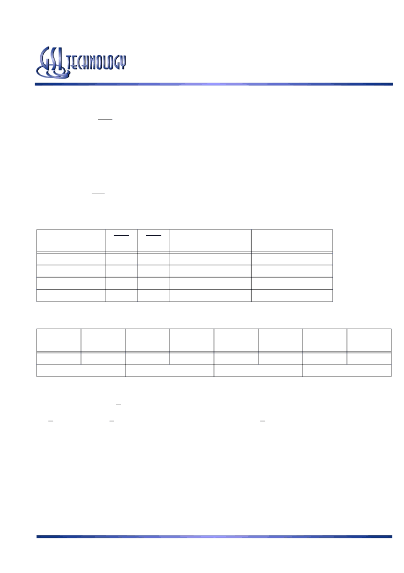
Example x18 RAM Write Sequence using Byte Write Enables
Data In Sample
Time
BW0
BW1
D0–D8
D9–D17
Beat 1
0
1
Data In
Don’t Care
Beat 2
1
0
Don’t Care
Data In
Beat 3
0
0
Data In
Data In
Beat 4
1
0
Don’t Care
Data In
Resulting Write Operation
Byte 1
D0–D8
Byte 2
D9–D17
Byte 1
D0–D8
Byte 2
D9–D17
Byte 1
D0–D8
Byte 2
D9–D17
Byte 1
D0–D8
Byte 2
D9–D17
Written
Unchanged
Unchanged
Written
Written
Written
Unchanged
Written
Beat 1
Beat 2
Beat 3
Beat 4
Output Register Control
SigmaQuad-II SRAMs offer two mechanisms for controlling the output data registers. Typically, control is handled by the Output
Register Clock inputs, C and C. The Output Register Clock inputs can be used to make small phase adjustments in the firing of the
output registers by allowing the user to delay driving data out as much as a few nanoseconds beyond the next rising edges of the K
and K clocks. If the C and C clock inputs are tied high, the RAM reverts to K and K control of the outputs, allowing the RAM to
function as a conventional pipelined read SRAM.
相關(guān)PDF資料 |
PDF描述 |
|---|---|
| GS8662D08E-200I | 72Mb SigmaQuad-II Burst of 4 SRAM |
| GS8662D08E-250 | 72Mb SigmaQuad-II Burst of 4 SRAM |
| GS8662D08E-250I | 72Mb SigmaQuad-II Burst of 4 SRAM |
| GS8662D08E-300 | 72Mb SigmaQuad-II Burst of 4 SRAM |
| GS8662D08E-300I | 72Mb SigmaQuad-II Burst of 4 SRAM |
相關(guān)代理商/技術(shù)參數(shù) |
參數(shù)描述 |
|---|---|
| GS8662D08E-200I | 制造商:GSI 制造商全稱:GSI Technology 功能描述:72Mb SigmaQuad-II Burst of 4 SRAM |
| GS8662D08E-250 | 制造商:GSI 制造商全稱:GSI Technology 功能描述:72Mb SigmaQuad-II Burst of 4 SRAM |
| GS8662D08E-250I | 制造商:GSI 制造商全稱:GSI Technology 功能描述:72Mb SigmaQuad-II Burst of 4 SRAM |
| GS8662D08E-300 | 制造商:GSI 制造商全稱:GSI Technology 功能描述:72Mb SigmaQuad-II Burst of 4 SRAM |
| GS8662D08E-300I | 制造商:GSI 制造商全稱:GSI Technology 功能描述:72Mb SigmaQuad-II Burst of 4 SRAM |
發(fā)布緊急采購,3分鐘左右您將得到回復(fù)。