- 您現(xiàn)在的位置:買賣IC網(wǎng) > PDF目錄370367 > GMS82512 (Hynix Semiconductor Inc.) 8-BIT SINGLE-CHIP MICROCONTROLLERS PDF資料下載
參數(shù)資料
| 型號: | GMS82512 |
| 廠商: | Hynix Semiconductor Inc. |
| 元件分類: | 8位微控制器 |
| 英文描述: | 8-BIT SINGLE-CHIP MICROCONTROLLERS |
| 中文描述: | 8位單晶片微控制器 |
| 文件頁數(shù): | 24/110頁 |
| 文件大?。?/td> | 1980K |
| 代理商: | GMS82512 |
第1頁第2頁第3頁第4頁第5頁第6頁第7頁第8頁第9頁第10頁第11頁第12頁第13頁第14頁第15頁第16頁第17頁第18頁第19頁第20頁第21頁第22頁第23頁當(dāng)前第24頁第25頁第26頁第27頁第28頁第29頁第30頁第31頁第32頁第33頁第34頁第35頁第36頁第37頁第38頁第39頁第40頁第41頁第42頁第43頁第44頁第45頁第46頁第47頁第48頁第49頁第50頁第51頁第52頁第53頁第54頁第55頁第56頁第57頁第58頁第59頁第60頁第61頁第62頁第63頁第64頁第65頁第66頁第67頁第68頁第69頁第70頁第71頁第72頁第73頁第74頁第75頁第76頁第77頁第78頁第79頁第80頁第81頁第82頁第83頁第84頁第85頁第86頁第87頁第88頁第89頁第90頁第91頁第92頁第93頁第94頁第95頁第96頁第97頁第98頁第99頁第100頁第101頁第102頁第103頁第104頁第105頁第106頁第107頁第108頁第109頁第110頁
GMS81508B/16B/24B, GMS82512/16/24
MAY. 2001 Ver 2.0
21
8. MEMORY ORGANIZATION
The GMS81508B/16B/24B and GMS82512/16/24 have
separate address spaces for Program memory and Data
Memory. Program memory can only be read, not written
to. It can be up to 24K bytes of Program memory. Data
memory can be read and written to up to 448 bytes includ-
ing the stack area.
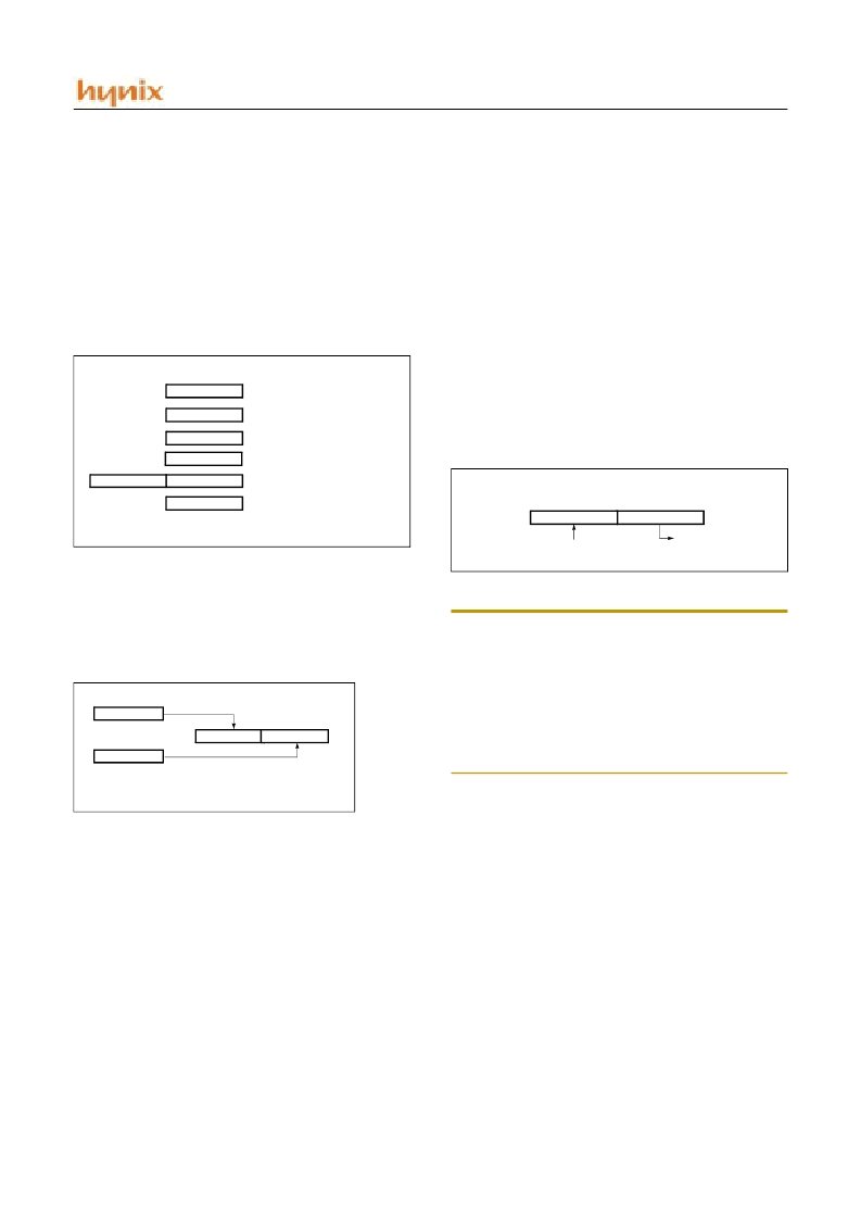
8.1 Registers
This device has six registers that are the Program Counter
(PC), a Accumulator (A), two index registers (X, Y), the
Stack Pointer (SP), and the Program Status Word (PSW).
The Program Counter consists of 16-bit register.
Figure 8-1 Configuration of Registers
Accumulator:
The Accumulator is the 8-bit general pur-
pose register, used for data operation such as transfer, tem-
porary saving, and conditional judgement, etc.
The Accumulator can be used as a 16-bit register with Y
Register as shown below.
Figure 8-2 Configuration of YA 16-bit Register
X, Y Registers
: In the addressing mode which uses these
index registers, the register contents are added to the spec-
ified address, which becomes the actual address. These
modes are extremely effective for referencing subroutine
tables and memory tables. The index registers also have in-
crement, decrement, comparison and data transfer func-
tions, and they can be used as simple accumulators.
Stack Pointer
: The Stack Pointer is an 8-bit register used
for occurrence interrupts and calling out subroutines. Stack
Pointer identifies the location in the stack to be accessed
(save or restore).
Generally, SP is automatically updated when a subroutine
call is executed or an interrupt is accepted. However, if it
is used in excess of the stack area permitted by the data
memory allocating configuration, the user-processed data
may be lost.
The stack can be located at any position within 100
H
to
1FF
H
of the internal data memory. The SP is not initialized
by hardware, requiring to write the initial value (the loca-
tion with which the use of the stack starts) by using the ini-
tialization routine. Normally, the initial value of “FE
H
” is
used.
Note:
The Stack Pointer must be initialized by software be-
cause its value is undefined after RESET.
Example: To initialize the SP
LDX
TXSP
#0FEH
; SP
←
FEH
Address 01FF
H
can not be used as stack. Don not use
1FF
H
, or malfunction would be occurred.
Program Counter
: The Program Counter is a 16-bit wide
which consists of two 8-bit registers, PCH and PCL. This
counter indicates the address of the next instruction to be
executed. In reset state, the program counter has reset rou-
tine address (PC
H
:0FF
H
, PC
L
:0FE
H
).
Program Status Word
: The Program Status Word (PSW)
contains several bits that reflect the current state of the
CPU. The PSW is described in Figure 8-3. It contains the
Negative flag, the Overflow flag, the Break flag the Half
Carry (for BCD operation), the Interrupt enable flag, the
Zero flag, and the Carry flag.
[Carry flag C]
This flag stores any carry or borrow from the ALU of CPU
after an arithmetic operation and is also changed by the
Shift Instruction or Rotate Instruction.
ACCUMULATOR
X REGISTER
Y REGISTER
STACK POINTER
PROGRAM COUNTER
PROGRAM STATUS
X
A
SP
Y
PCL
PSW
PCH
Two 8-bit Registers can be used as a “YA” 16-bit Register
Y
A
Y
A
SP
01
H
Stack Address (100
H
~ 1FE
H
)
8 7
Bit 15
Bit 0
Hardware fixed
00
H
~FE
H
相關(guān)PDF資料 |
PDF描述 |
|---|---|
| GMS81516BT | [General Purpose(1) : ADC/ LED/ SCI/ PWM] |
| GMS81524B | 8-BIT SINGLE-CHIP MICROCONTROLLERS |
| GMS81508BLQ | 8-BIT SINGLE-CHIP MICROCONTROLLERS |
| GMS81516BLQ | 8-BIT SINGLE-CHIP MICROCONTROLLERS |
| GMS81524BLQ | 8-BIT SINGLE-CHIP MICROCONTROLLERS |
相關(guān)代理商/技術(shù)參數(shù) |
參數(shù)描述 |
|---|---|
| GMS82512K | 制造商:HYNIX 制造商全稱:Hynix Semiconductor 功能描述:8-BIT SINGLE-CHIP MICROCONTROLLERS |
| GMS82512Q | 制造商:HYNIX 制造商全稱:Hynix Semiconductor 功能描述:8-BIT SINGLE-CHIP MICROCONTROLLERS |
| GMS82516 | 制造商:HYNIX 制造商全稱:Hynix Semiconductor 功能描述:8-BIT SINGLE-CHIP MICROCONTROLLERS |
| GMS82516K | 制造商:HYNIX 制造商全稱:Hynix Semiconductor 功能描述:8-BIT SINGLE-CHIP MICROCONTROLLERS |
| GMS82516Q | 制造商:HYNIX 制造商全稱:Hynix Semiconductor 功能描述:8-BIT SINGLE-CHIP MICROCONTROLLERS |
發(fā)布緊急采購,3分鐘左右您將得到回復(fù)。