- 您現(xiàn)在的位置:買賣IC網(wǎng) > PDF目錄357857 > G6WK-1P-24VDC RF RELAY, SPDT, LATCHED, 0.015A (COIL), 24VDC (COIL), 360mW (COIL), 0.5A (CONTACT), 30VDC (CONTACT), 2500MHz, THROUGH HOLE-STRAIGHT MOUNT PDF資料下載
參數(shù)資料
| 型號: | G6WK-1P-24VDC |
| 元件分類: | 射頻繼電器 |
| 英文描述: | RF RELAY, SPDT, LATCHED, 0.015A (COIL), 24VDC (COIL), 360mW (COIL), 0.5A (CONTACT), 30VDC (CONTACT), 2500MHz, THROUGH HOLE-STRAIGHT MOUNT |
| 文件頁數(shù): | 8/8頁 |
| 文件大?。?/td> | 375K |
| 代理商: | G6WK-1P-24VDC |
G6W
G6W
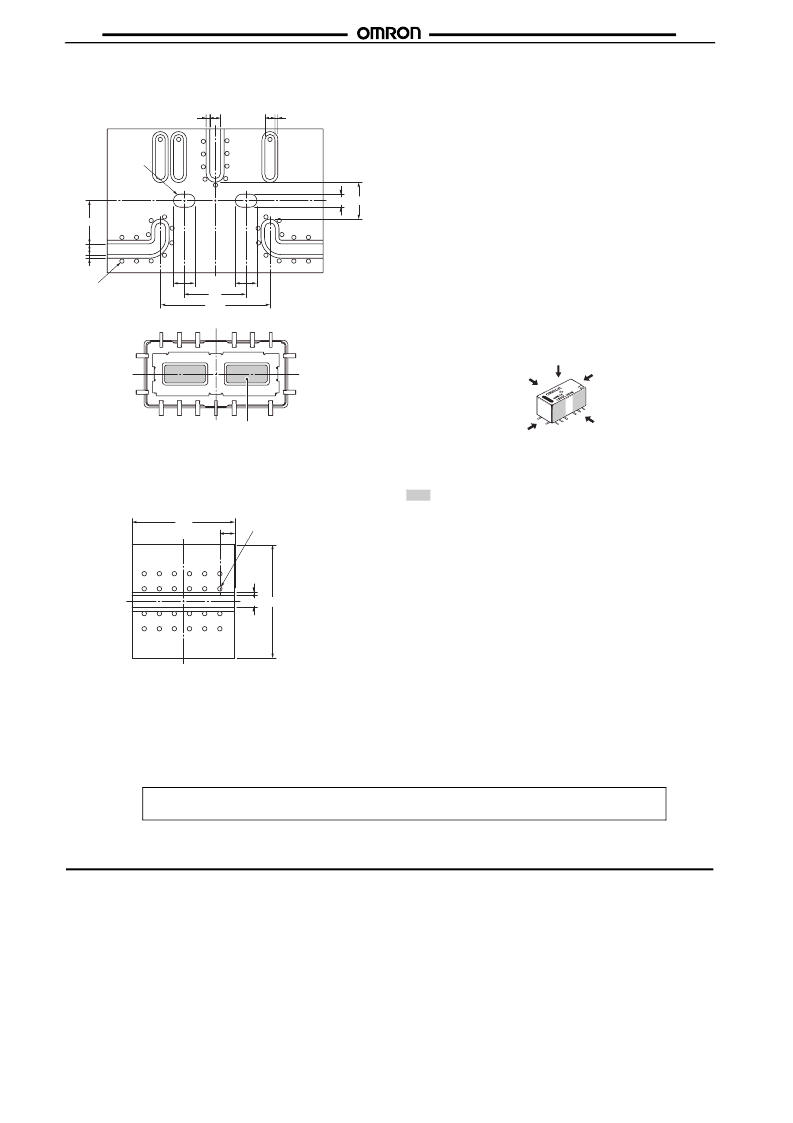
SMD-type substrate
Substrate: t-0.8 BT resin (Dielectric constant at 2 GHz: 3.37)
Note:
To obtain high-frequency characteristics close to the
charts shown on page 2, solder the convex point on the
undersurface of the relay to the ground pattern of the
substrate.
Base plate for high-frequency characteristic compensation
Note:
The above compensation plate is used to measure the
loss by the relay.
The relay loss is determined by subtracting the data
measured for a compensation base plate from those for a
high-frequency characteristics measuring substrate
mounted with a relay.
Handling
Leave the Relays packed until just prior to mounting them.
Dropping the relay may cause damage to its functional capability.
Never use the relay if it is dropped.
Protect the relays from direct sunlight during operation, storage,
and transportation and keep the relays under normal temperature,
humidity, and pressure.
Soldering
Solder: JIS Z3282, H63A
Soldering temperature: Approx. 250
°
C (At 260
°
C if the DWS
method is used.)
Soldering time: Approx. 5 s max. (approx. 2 s for the first time and
approx. 3 s for the second time if the DWS method is used.)
Be sure to adjust the level of the molten solder so that the solder
will not overflow onto the PCB.
Claw Securing Force During Automatic Insertion
During automatic insertion of Relays, make sure to set the
securing force of the claws to the following values so that the
Relay characteristics will be maintained.
Latching Relay Mounting
Make sure that the vibration or shock that is generated from other
devices, such as relays in operation, on the same panel and
imposed on the Latching Relay does not exceed the rated value,
otherwise the Latching Relay that has been set may be reset or
vice versa. The Latching Relay is reset before shipping. If
excessive vibration or shock is imposed, however, the Latching
Relay may be set accidentally. Be sure to apply a reset signal
before use.
Coating
Relays mounted on PCBs may be coated or washed. Do not
apply silicone coating or detergent containing silicone, otherwise
the silicone coating or detergent may remain on the surface of the
Relays.
Convex position
15.24
5.12
1.8
1.5
0.5
1.4
0.4
8.6
3
Thirty one, 0.6-dia.,
through-hole
1.5
6
0.5
3
Undersurface of relay
Through-
hole
15
0.5
13.6
1.5
2
Twenty four, 0.6-dia.,
through-hole
Secure the claws to the area indicated by shading.
Do not attach them to the center area or to only part of the
Relay.
A
C
B
Direction A: 4.90 N max.
Direction B: 9.80 N max.
Direction C: 9.80 N max.
In the interest of product improvement, specifications are subject to change without notice.
OMRON Corporation
Electronic Components Company
ALL DIMENSIONS SHOWN ARE IN MILLIMETERS.
To convert millimeters into inches, multiply by 0.03937. To convert grams into ounces, multiply by 0.03527.
Cat. No. K120-E1-01
Electronic & Mechanical Components Division H.Q.
Low Signal Relay Division
2-1, 2-Chome, Nishikusatsu, Kusatsu-City,
Shiga, 525-0035 Japan
Tel: (81)77-565-5481/Fax: (81)77-565-5581
Printed in Japan
0702-2M (0702) (B)
相關(guān)PDF資料 |
PDF描述 |
|---|---|
| G8198-02 | PIN PHOTO DIODE |
| G8JN-1C6T-DC12 | POWER/SIGNAL RELAY, SPDT, MOMENTARY, 0.16A (COIL), 12VDC (COIL), 1920mW (COIL), 35A (CONTACT), 16VDC (CONTACT), PANEL MOUNT |
| G8JN-1C6T-F-DC12 | POWER/SIGNAL RELAY, SPDT, MOMENTARY, 0.16A (COIL), 12VDC (COIL), 1920mW (COIL), 35A (CONTACT), 16VDC (CONTACT), PANEL MOUNT |
| G8JN-1C6T-F-R-DC12 | POWER/SIGNAL RELAY, SPDT, MOMENTARY, 0.16A (COIL), 12VDC (COIL), 1920mW (COIL), 35A (CONTACT), 16VDC (CONTACT), PANEL MOUNT |
| G8JN-1C6T-R-DC12 | POWER/SIGNAL RELAY, SPDT, MOMENTARY, 0.16A (COIL), 12VDC (COIL), 1920mW (COIL), 35A (CONTACT), 16VDC (CONTACT), PANEL MOUNT |
相關(guān)代理商/技術(shù)參數(shù) |
參數(shù)描述 |
|---|---|
| G6WK1PDC12 | 制造商:Omron Electronic Components LLC 功能描述:RELAY RF SPDT 10MA 12V |
| G6WK1PDC24 | 制造商:Omron Electronic Components LLC 功能描述:RELAY RF SPDT 10MA 24V |
| G6WK1PDC3 | 制造商:Omron Electronic Components LLC 功能描述:RELAY RF SPDT 10MA 3V |
| G6WK-1P-DC4.5 | 功能描述:高頻/射頻繼電器 5 GHZ SPDT 4.5VDC FREQ RoHS:否 制造商:Omron Electronics 觸點形式:2 Form C (DPDT-BM) 觸點電流額定值: 線圈電壓:5 VDC 線圈類型:Non-Latching 頻率: 功耗:100 mW 端接類型:Solder Terminal 絕緣:20 dB to 30 dB at 1 GHz 介入損耗:0.2 dB at 1 GHz |
| G6WK1PDC45 | 制造商:Omron Electronic Components LLC 功能描述:RELAY RF SPDT 10MA 4.5V |
發(fā)布緊急采購,3分鐘左右您將得到回復(fù)。