- 您現(xiàn)在的位置:買賣IC網(wǎng) > PDF目錄384300 > G3VM-W-S (Omron Electronics LLC) MOSFET RELAY PDF資料下載
參數(shù)資料
| 型號: | G3VM-W-S |
| 廠商: | Omron Electronics LLC |
| 英文描述: | MOSFET RELAY |
| 中文描述: | MOSFET繼電器 |
| 文件頁數(shù): | 2/4頁 |
| 文件大小: | 71K |
| 代理商: | G3VM-W-S |
G3VM-W
G3VM-W
2
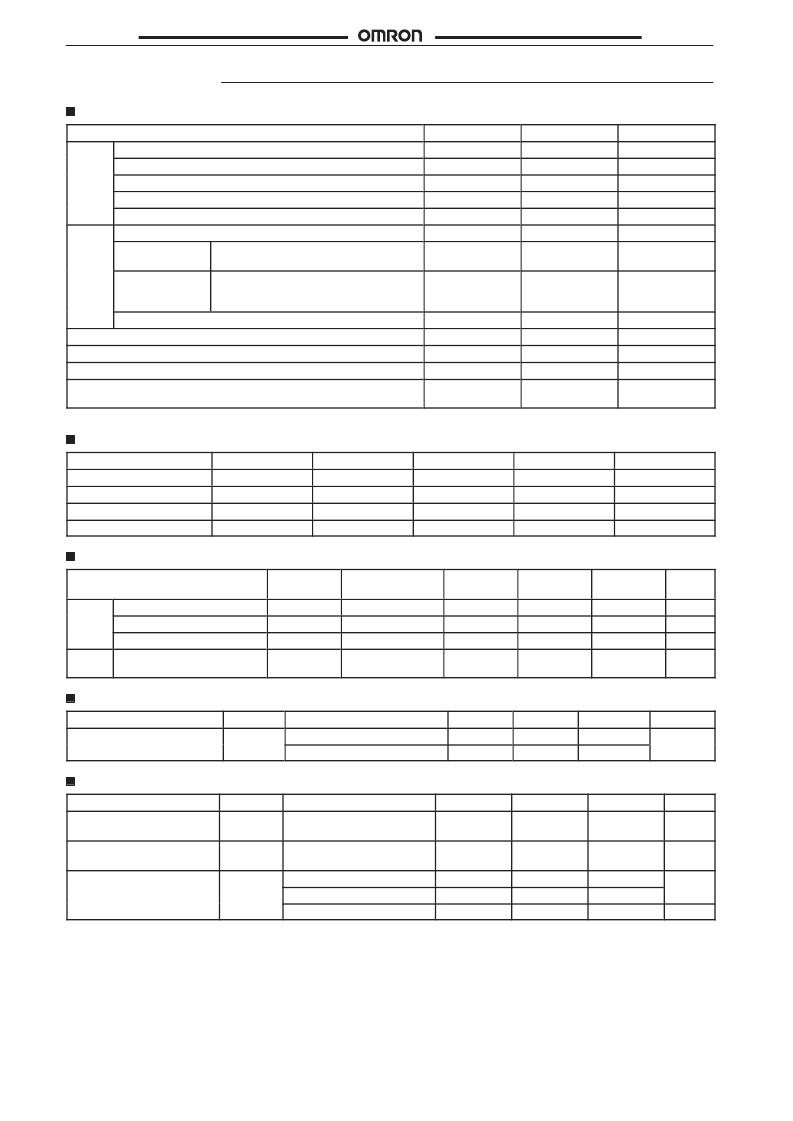
Specifications
Absolute Maximum Ratings (Ta = 25
°
C)
Item
Symbol
Rating
Unit
Input
LED forward current
LED forward current reduction rate (Ta
Repetitive peak LED forward current (100
μ
s pulse)
LED reverse voltage
Connection temperature
Output dielectric strength
Continuous load
current
ON current
reduction rate
(Ta
25 C)
Connection temperature
Storage temperature
Operating temperature
Soldering temperature (10 s)
Dielectric strength (AC for 1 min with ambient humidity of 60% or
less) (see note)
I
F
50
–0.5
1
5
125
350
120
mA
mA/ C
A
V
C
V
mA
25 C)
I
F
/ C
I
FP
V
R
T
j
V
OFF
I
O
Output
Current per channel
Current per channel
I
ON
/ C
–1.2
mA/ C
T
j
T
stg
T
a
T
sol
V
I-O
125
–55 to 100
–20 to 85
260
2,500
C
C
C
C
V
rms
Note:
Recommended Operating Conditions
Apply voltage between a group of pins 1, 2, and 3, 4 and that of pins 8, 7 and 6, 5.
Item
Symbol
Minimum
Typical
Maximum
Unit
Operating
voltage
Forward current
Continuous load current
Operating temperature
V
DD
I
F
I
O
Ta
---
5.0
---
–20
---
7.5
---
---
280
25
100
65
V
mA
mA
C
Electrical Characteristics (Ta = 25
°
C)
Item
Symbol
Measurement
conditions
I
F
=10 mA
V
R
=5 V
V=0, , f=1MHZ
V
OFF
=350 V
Minimum
Typical
Maximum
Unit
Input
LED forward current
Reverse current
Capacity between terminals
Current leakage when the
relay is open
V
F
I
R
C
T
I
LEAK
1.0
---
---
---
1.15
---
30
---
1.3
10
---
1
V
μ
A
pF
μ
A
Output
Connection Characteristics (Ta = 25
°
C)
Item
Ma
output ON
Symbol
R
ON
Measurement
conditions
I
ON
=100 mA, I
F
=10 mA
I
ON
=20 to 100 mA, I
F
=10 mA
Minimum
---
---
Typical
22
26
Maximum
35
40
Unit
u
es s a ce
Insulation Characteristics (Ta = 25
°
C)
Item
Floating capacity between
I/O terminals
Symbol
C
I-O
Measurement
conditions
V
S
=0, f=1MH
Z
Minimum
---
Typical
0.8
Maximum
---
Unit
pF
Insulation resistance
R
I-O
V
S
=0, operating ambient
humidity:
60%
5 x 10
10
10
14
---
Dielectric strength
e ec
c s e g
V
I-O
AC for 1 min
AC for 1 s in oil
DC for 1 min in oil
2,500
---
---
---
5,000
5,000
---
---
---
V
rms
V
dc
相關(guān)PDF資料 |
PDF描述 |
|---|---|
| G3VM-WF | MOSFET RELAY |
| G3VM-WF-S | MOSFET RELAY |
| G55C816PEI-4 | CMOS 8/16-BIT MICROPROCESSOR FAMILY |
| G55C816PEI-5 | CMOS 8/16-BIT MICROPROCESSOR FAMILY |
| G55C816PI-4 | CMOS 8/16-BIT MICROPROCESSOR FAMILY |
相關(guān)代理商/技術(shù)參數(shù) |
參數(shù)描述 |
|---|---|
| G3VM-W-S | 制造商:Omron Electronic Components LLC 功能描述:RELAY MOSFET DPNO |
| G3VMXN | 制造商:Omron Corporation 功能描述:- Rail/Tube |
| G3VMXNFS | 制造商:Omron Corporation 功能描述: |
| G3VMXNS | 制造商:Omron Corporation 功能描述: |
| G3X | 制造商:Zoom 功能描述:G3X USB Effects Console with Expression Pedal |
發(fā)布緊急采購,3分鐘左右您將得到回復(fù)。