- 您現(xiàn)在的位置:買賣IC網(wǎng) > PDF目錄370146 > FA7630CE Analog IC PDF資料下載
參數(shù)資料
| 型號: | FA7630CE |
| 英文描述: | Analog IC |
| 中文描述: | 模擬IC |
| 文件頁數(shù): | 1/5頁 |
| 文件大小: | 64K |
| 代理商: | FA7630CE |

FA7630CP(E)
1
I
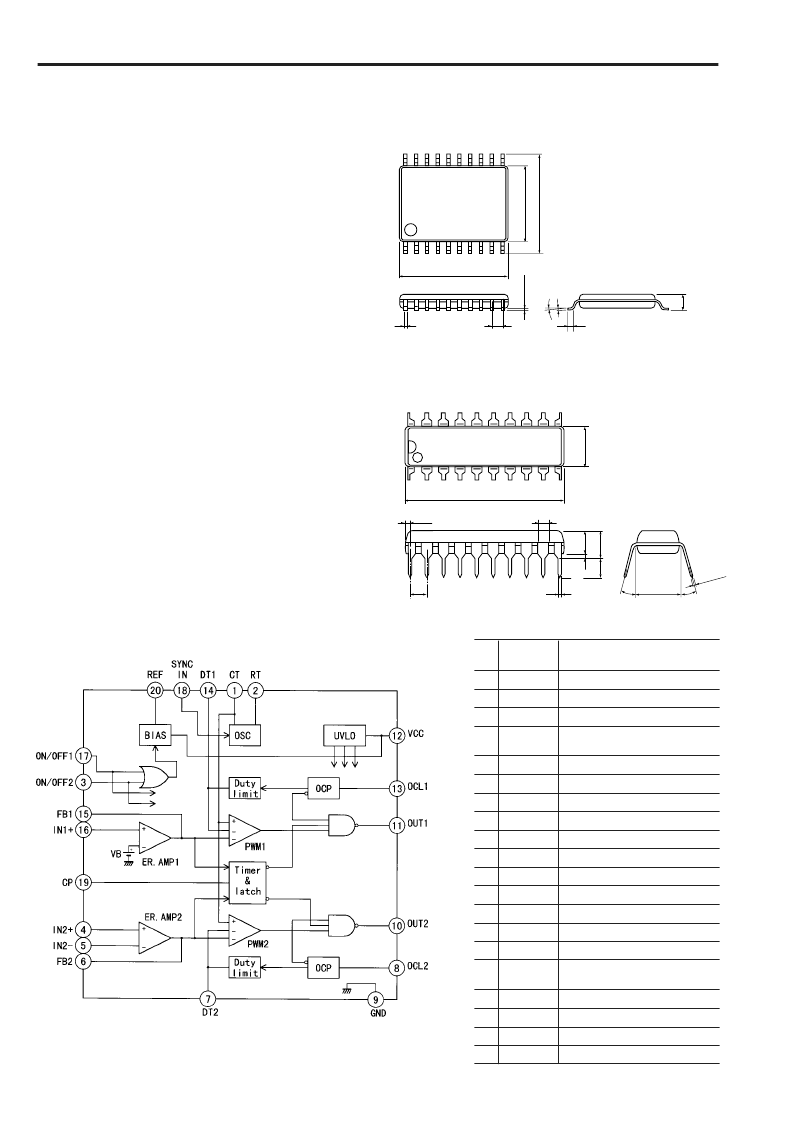
Block diagram
Pin
No.
Pin
symbol
CT
RT
ON/OFF2
Output ON/OFF control 2
IN2+
Non-inverting input to error
amplifier
IN2
–
Inverting input to error amplifier
FB2
Error amplifier output
DT2
Dead time adjustment
OCL2
Overcurrent limiting circuit 2
GND
Ground
OUT2
CH.2 output
OUT1
CH.1 output
VCC
Power supply
OCL1
Overcurrent limiting circuit
DT1
Dead time adjustment
FB1
Error amplifier output
IN1+
Non-inverting input to error
amplifier
ON/OFF1
Output ON/OFF control 1
SYNC IN
Synchronizing signal input
CP
Timer and latch circuit
REF
Reference voltage output
Description
1
Oscillator timing capacitor
2
Oscillator timing resistor
3
4
5
6
7
8
9
10
11
12
13
14
15
16
17
18
19
20
I
Dimensions, mm
á
SSOP-20
1
7.2
10
11
20
5
0.6
0
0.65
7
±
0
0
±
0
0.3
0
+
2
á
DIP-20
1
20
11
10
24.4
6
7.62
3
5
1.52
0.77
2
0
0~15
0~15
0.46
±
0.1
2.54
±
0.25
0.25
+0.1
Bipolar IC
For Switching Power Supply Control
I
Description
The FA7630CP(E) is dual channel PWM-type switching power
supply control IC.
This IC can drive Pch-MOSFET directly and is optimum for
large power DC-DC converter.
This IC has all the necessary protection functions for a power
MOSFET. It is optimum for a portable equipment power
supply which uses low-voltage input to output comparably
large power.
I
Features
Dual channel PWM-type switching power supply control
±
2.6% (V
REF
) and
±
3% (V
B
) reference voltage
Low voltage operation (Vcc: 5 to 20V)
Drive circuit for connecting a Pch-MOSFET
Overload cutoff circuit with timer latch circuit
Soft start circuit
Undervoltage lockout function (UVLO)
Pulse-by-pulse overcurrent limiting function
Output ON/OFF control function for each channel
Master-slave synchronized operation without external
components
Maximum operating frequency is 500kHz
相關(guān)PDF資料 |
PDF描述 |
|---|---|
| FA80486GXSF-16 | 32-Bit Microprocessor |
| FA80486GXSF-20 | 32-Bit Microprocessor |
| FA80486GXSF-25 | 32-Bit Microprocessor |
| FA80486GXSF-33 | 32-Bit Microprocessor |
| FA80486SXSF-25 | 32-Bit Microprocessor |
相關(guān)代理商/技術(shù)參數(shù) |
參數(shù)描述 |
|---|---|
| FA7630CP | 制造商:FUJI 制造商全稱:Fuji Electric 功能描述:Bipolar IC For Switching Power Supply Control |
| FA7630CPE | 制造商:FUJI 制造商全稱:Fuji Electric 功能描述:Bipolar IC For Switching Power Supply Control |
| FA765 | 制造商:Black Box Corporation 功能描述:MMJ Modular Adapter Kit, DB9 to MMJ, Male |
| FA766 | 制造商:Black Box Corporation 功能描述:COMPUTER ACCESSORY |
| FA76AXPM1 | 制造商:Carling Technologies 功能描述:F-Series Toggle Switch |
發(fā)布緊急采購,3分鐘左右您將得到回復。