- 您現(xiàn)在的位置:買(mǎi)賣(mài)IC網(wǎng) > PDF目錄97930 > EPM7256AEFC256-10 PDF資料下載
參數(shù)資料
| 型號(hào): | EPM7256AEFC256-10 |
| 文件頁(yè)數(shù): | 21/60頁(yè) |
| 文件大?。?/td> | 1041K |
| 代理商: | EPM7256AEFC256-10 |
第1頁(yè)第2頁(yè)第3頁(yè)第4頁(yè)第5頁(yè)第6頁(yè)第7頁(yè)第8頁(yè)第9頁(yè)第10頁(yè)第11頁(yè)第12頁(yè)第13頁(yè)第14頁(yè)第15頁(yè)第16頁(yè)第17頁(yè)第18頁(yè)第19頁(yè)第20頁(yè)當(dāng)前第21頁(yè)第22頁(yè)第23頁(yè)第24頁(yè)第25頁(yè)第26頁(yè)第27頁(yè)第28頁(yè)第29頁(yè)第30頁(yè)第31頁(yè)第32頁(yè)第33頁(yè)第34頁(yè)第35頁(yè)第36頁(yè)第37頁(yè)第38頁(yè)第39頁(yè)第40頁(yè)第41頁(yè)第42頁(yè)第43頁(yè)第44頁(yè)第45頁(yè)第46頁(yè)第47頁(yè)第48頁(yè)第49頁(yè)第50頁(yè)第51頁(yè)第52頁(yè)第53頁(yè)第54頁(yè)第55頁(yè)第56頁(yè)第57頁(yè)第58頁(yè)第59頁(yè)第60頁(yè)
28
Altera Corporation
MAX 7000A Programmable Logic Device Data Sheet
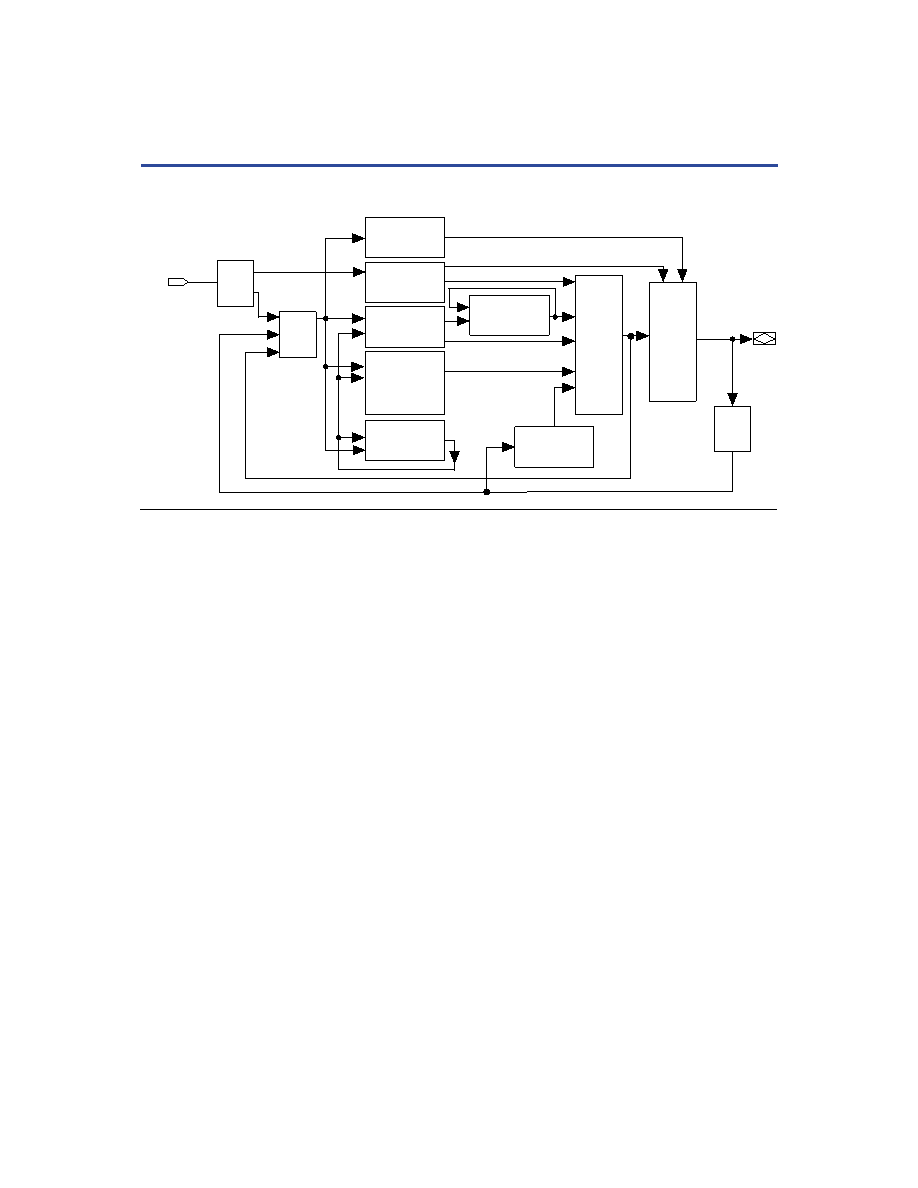
Figure 11. MAX 7000A Timing Model
The timing characteristics of any signal path can be derived from the
timing model and parameters of a particular device. External timing
parameters, which represent pin-to-pin timing delays, can be calculated
as the sum of internal parameters. Figure 12 shows the timing relationship
between internal and external delay parameters.
information.
Logic Array
Delay
t LAD
Output
Delay
t OD3
t OD2
t OD1
t XZ
Z
t X1
t ZX2
t ZX3
Input
Delay
t IN
Register
Delay
t SU
t H
t PRE
t CLR
t RD
t COMB
t FSU
t FH
PIA
Delay
t PIA
Shared
Expander Delay
t SEXP
Register
Control Delay
t LAC
t IC
t EN
I/O
Delay
t IO
Global Control
Delay
t GLOB
Internal Output
Enable Delay
t IOE
Parallel
Expander Delay
t PEXP
Fast
Input Delay
t FIN
相關(guān)PDF資料 |
PDF描述 |
|---|---|
| EPM7256AEFC256-5 | |
| EPM7256AEFC256-7 | |
| EPM7256AEFI100-7 | |
| EPM7256AEFI256-7 | |
| EPM7256AEQC208-10 | |
相關(guān)代理商/技術(shù)參數(shù) |
參數(shù)描述 |
|---|---|
| EPM7256AEFC256-10N | 功能描述:CPLD - 復(fù)雜可編程邏輯器件 CPLD - MAX 7000 256 Macro 164 IOs RoHS:否 制造商:Lattice 系列: 存儲(chǔ)類(lèi)型:EEPROM 大電池?cái)?shù)量:128 最大工作頻率:333 MHz 延遲時(shí)間:2.7 ns 可編程輸入/輸出端數(shù)量:64 工作電源電壓:3.3 V 最大工作溫度:+ 90 C 最小工作溫度:0 C 封裝 / 箱體:TQFP-100 |
| EPM7256AEFC256-5 | 功能描述:CPLD - 復(fù)雜可編程邏輯器件 CPLD - MAX 7000 256 Macro 164 IOs RoHS:否 制造商:Lattice 系列: 存儲(chǔ)類(lèi)型:EEPROM 大電池?cái)?shù)量:128 最大工作頻率:333 MHz 延遲時(shí)間:2.7 ns 可編程輸入/輸出端數(shù)量:64 工作電源電壓:3.3 V 最大工作溫度:+ 90 C 最小工作溫度:0 C 封裝 / 箱體:TQFP-100 |
| EPM7256AEFC2565N | 制造商:Altera Corporation 功能描述: |
| EPM7256AEFC256-5N | 功能描述:CPLD - 復(fù)雜可編程邏輯器件 CPLD - MAX 7000 256 Macro 164 IOs RoHS:否 制造商:Lattice 系列: 存儲(chǔ)類(lèi)型:EEPROM 大電池?cái)?shù)量:128 最大工作頻率:333 MHz 延遲時(shí)間:2.7 ns 可編程輸入/輸出端數(shù)量:64 工作電源電壓:3.3 V 最大工作溫度:+ 90 C 最小工作溫度:0 C 封裝 / 箱體:TQFP-100 |
| EPM7256AEFC256-7 | 功能描述:CPLD - 復(fù)雜可編程邏輯器件 CPLD - MAX 7000 256 Macro 164 IOs RoHS:否 制造商:Lattice 系列: 存儲(chǔ)類(lèi)型:EEPROM 大電池?cái)?shù)量:128 最大工作頻率:333 MHz 延遲時(shí)間:2.7 ns 可編程輸入/輸出端數(shù)量:64 工作電源電壓:3.3 V 最大工作溫度:+ 90 C 最小工作溫度:0 C 封裝 / 箱體:TQFP-100 |
發(fā)布緊急采購(gòu),3分鐘左右您將得到回復(fù)。