- 您現(xiàn)在的位置:買(mǎi)賣(mài)IC網(wǎng) > PDF目錄93232 > DRBD-11-AA-01AA (MOOG COMPONENTS GROUP) POSITION, ROTARY SENSOR-RESOLVER, 15%, 1-4V, CYLINDRICAL PDF資料下載
參數(shù)資料
| 型號(hào): | DRBD-11-AA-01AA |
| 廠商: | MOOG COMPONENTS GROUP |
| 元件分類(lèi): | Position, Rotary, Synchro/Resolver Sensor |
| 英文描述: | POSITION, ROTARY SENSOR-RESOLVER, 15%, 1-4V, CYLINDRICAL |
| 文件頁(yè)數(shù): | 3/4頁(yè) |
| 文件大?。?/td> | 466K |
| 代理商: | DRBD-11-AA-01AA |
98
Moog Components Group
www.moog.com
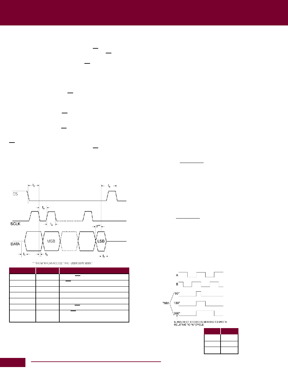
TIMING CHARACTERISTICS
Parameter
Units
Test Conditions / Notes
t
1
150ns max
CS to DATA enable
t
2
600ns min
CS to ist SCLK negative edge
t
3
250ns min
SCLK low pulse
t
4
250ns min
SCLK high pulse
t
5
100ns max SCLK negative edge to DATA valid
t
6
250ns min
CS high pulse width
t
7
150ns max
CS high to DATA high Z
(BUS Relinquish)
SCLK can only be applyed after t
2 has elapsed.
NOTES:
1. Timing data are not 100% production tested. Sample tested at +25°C only to
ensure conformance to data sheet limits. Logic output timing tests carried out
using 10pF, 100ka load.
2. Capacitance of DATA pin in high impedance state = 15 pF.
Absolute Position Output
Serial Interface
Absolute angular position is represented by serial binary data and
is extracted via a three wire interface: DATA, CS and SCLK. The
DATA output is held in a high impedance state when CS is HI.
Upon the application of a LOGIC LO to the CS pin. The DATA output
is enabled and the current angular information is transferred from
the counters to the serial interface. Data is retrieved by appling an
external clock to the SCLK pin. The maximum data rate of the SCLK
is 2MHz. To ensure secure data retrieval it is important to note that
SCLK should not be applied until a minimum period of 600ns after
the application of a LOGIC LO to CS. Data is then clocked out, MSB
rst. On successive negative edges of the SCLK: 12 clock edges
are required to extract the full 12 bits of data. Subsequent negtive
edges greater than the dened resolution of the converter will clock
zeros from the data output if CS remains in a low state.
If a resolution of less than 12 bits is required, the data access can
be terminated by releasing CS after the required number of bits
have been read.
CS can be released a minimum of 100ns after the last negative
edge. If the user is reading data continuously, CS can be reapplied
a minimum of 250ns after it is released (see Figure 1).
The maximum read time is given by: (12-bits read @ 2 MHz) MAX
RD TIME = [600 + (12 x 500) + 250 +100] = 6.95 s
Incremental Encoder Output
The Incremental encoder emulation outputs A, B and NM are free
running and are always valid.
The digital resolver emulates a 1024-line encoder. Relating this
to converter resolution means one revolution produces 1024, A,
B Pulses. A leads B for increasing angular rotation. The addition
of the DIR output negates the need for external A and B direction
decode logic. DIR is HI for increasing angular rotation (CW shaft
rotation).
The North Marker Pulse is generated as the absolute angular
position passes through zero. The digital rsolver supports the three
industry standard widths controlled using the NMC pin. Figure 2
details the relationship between A, B and NM. The width of NM is
dened relative to the A cycle.
Unlike the incremental encoders, the digital resolver output is not
subject to error specications such as cycle error, eccentricity, pulse
and state width errors, count density and pulse error.
The maximum speed rating, N, of an encoder is calculated from
its maximum switching frequency, F
MAX, and its PPR (Pulse Per
Revolution).
60 x F
MAX
n =
PPR
The digital resolver A, B pulses are initiated from CLKOUT which
has a maximum frequency of 1.536 MHz. The equivalent en-
coder switching frequency is:
1/4 x 1.536 MHz = 384 kHz (4 UPDATES = 1 PULSE)
At 12 bits the PPR = 1024. Therefore the maximum speed, N, of
the digital resolver is:
60 x 384000
n =
= 22500 rpm
1024
This compares favorably with encoder specications where F
MAX
is specied from 20 kHz (photo diodes) to 125 kHz (laser based)
depending on the light system used. A 1024 line laser-based
encoder will have a maximum speed of 7300rpm.
The inclusion of A, B outputs allows the digital resolver solution
to replace optical encoders directly without the need to change or
upgrade existing application software.
Figure 1
Figure 2
Level
Width
+5 VDC
90°
0
180°
–5 VDC 360°
*Selectable with three - level
control pin “marker” default
to 90° using internal pull-up.
Resolvers
相關(guān)PDF資料 |
PDF描述 |
|---|---|
| DRD028ED013 | DISC TYPE DIELECTRIC RESONATOR, 23170 MHz - 25150 MHz |
| DRD028RE013 | DISC TYPE DIELECTRIC RESONATOR, 20400 MHz - 22100 MHz |
| DRD060RE027B | DISC TYPE DIELECTRIC RESONATOR, 9700 MHz - 10800 MHz |
| DRT051R020E022 | CYLINDRICAL TYPE DIELECTRIC RESONATOR, 11900 MHz - 13100 MHz |
| DRT060R020E027 | CYLINDRICAL TYPE DIELECTRIC RESONATOR, 10000 MHz - 11000 MHz |
相關(guān)代理商/技術(shù)參數(shù) |
參數(shù)描述 |
|---|---|
| DRBK-01 | 制造商:Qualtek Electronics Corporation 功能描述:DIN RAIL BOTTOM MOUNT 制造商:Qualtek Electronics Corporation 功能描述:Power Supplies |
| DRBK-02 | 制造商:Qualtek Electronics Corporation 功能描述:DIN RAIL BOTTOM MOUNT 制造商:Qualtek Electronics Corporation 功能描述:Power Supplies |
| DRBN600W0R1JC | 制造商:TOKEN 制造商全稱(chēng):Token Electronics Industry Co., Ltd. 功能描述:DR Round-Wirewound Power Resistors |
| DRBN600W0R1JG | 制造商:TOKEN 制造商全稱(chēng):Token Electronics Industry Co., Ltd. 功能描述:DR Round-Wirewound Power Resistors |
| DRBN600W0R1JN | 制造商:TOKEN 制造商全稱(chēng):Token Electronics Industry Co., Ltd. 功能描述:DR Round-Wirewound Power Resistors |
發(fā)布緊急采購(gòu),3分鐘左右您將得到回復(fù)。