- 您現(xiàn)在的位置:買賣IC網(wǎng) > PDF目錄1992 > CY28354OXC-400 (Silicon Laboratories Inc)IC BUFF 273MHZ 4DDR DIMM 48SSOP PDF資料下載
參數(shù)資料
| 型號(hào): | CY28354OXC-400 |
| 廠商: | Silicon Laboratories Inc |
| 文件頁(yè)數(shù): | 2/8頁(yè) |
| 文件大?。?/td> | 0K |
| 描述: | IC BUFF 273MHZ 4DDR DIMM 48SSOP |
| 標(biāo)準(zhǔn)包裝: | 30 |
| 類型: | 扇出緩沖器(分配) |
| PLL: | 無(wú) |
| 主要目的: | 存儲(chǔ)器,DDR |
| 輸入: | 時(shí)鐘 |
| 輸出: | 時(shí)鐘 |
| 電路數(shù): | 2 |
| 比率 - 輸入:輸出: | 1:12 |
| 差分 - 輸入:輸出: | 無(wú)/無(wú) |
| 頻率 - 最大: | 400MHz |
| 電源電壓: | 2.3 V ~ 2.7 V |
| 工作溫度: | 0°C ~ 85°C |
| 安裝類型: | * |
| 封裝/外殼: | * |
| 供應(yīng)商設(shè)備封裝: | * |
| 包裝: | * |
CY28354-400
.......................... Document #: 38-07615 Rev. *B Page 2 of 8
Serial Data Interface
To enhance the flexibility and function of the clock synthesizer,
a two-signal serial interface is provided. Through the Serial
Data Interface, various device functions such as individual
clock output buffers, etc., can be individually enabled or
disabled. The registers associated with the Serial Data
Interface initializes to their default setting upon power-up, and
therefore use of this interface is optional. Clock device register
changes are normally made upon system initialization, if any
are required. The interface can also be used during system
operation for power management functions.
Data Protocol
The clock driver serial protocol accepts Byte Write, Byte Read,
Block Write, and Block Read operation from the controller. For
Block Write/Read operation, the bytes must be accessed in
sequential order from lowest to highest byte (most significant
bit first) with the ability to stop after any complete byte has
been transferred. For Byte Write and Byte Read operations,
the system controller can access individual indexed bytes. The
offset of the indexed byte is encoded in the command code,
as described in Table 1. The Block Write and Block Read
protocol is outlined in Table 2.The slave receiver address is
D2/DC depending on the state of the ADDRSEL pin.
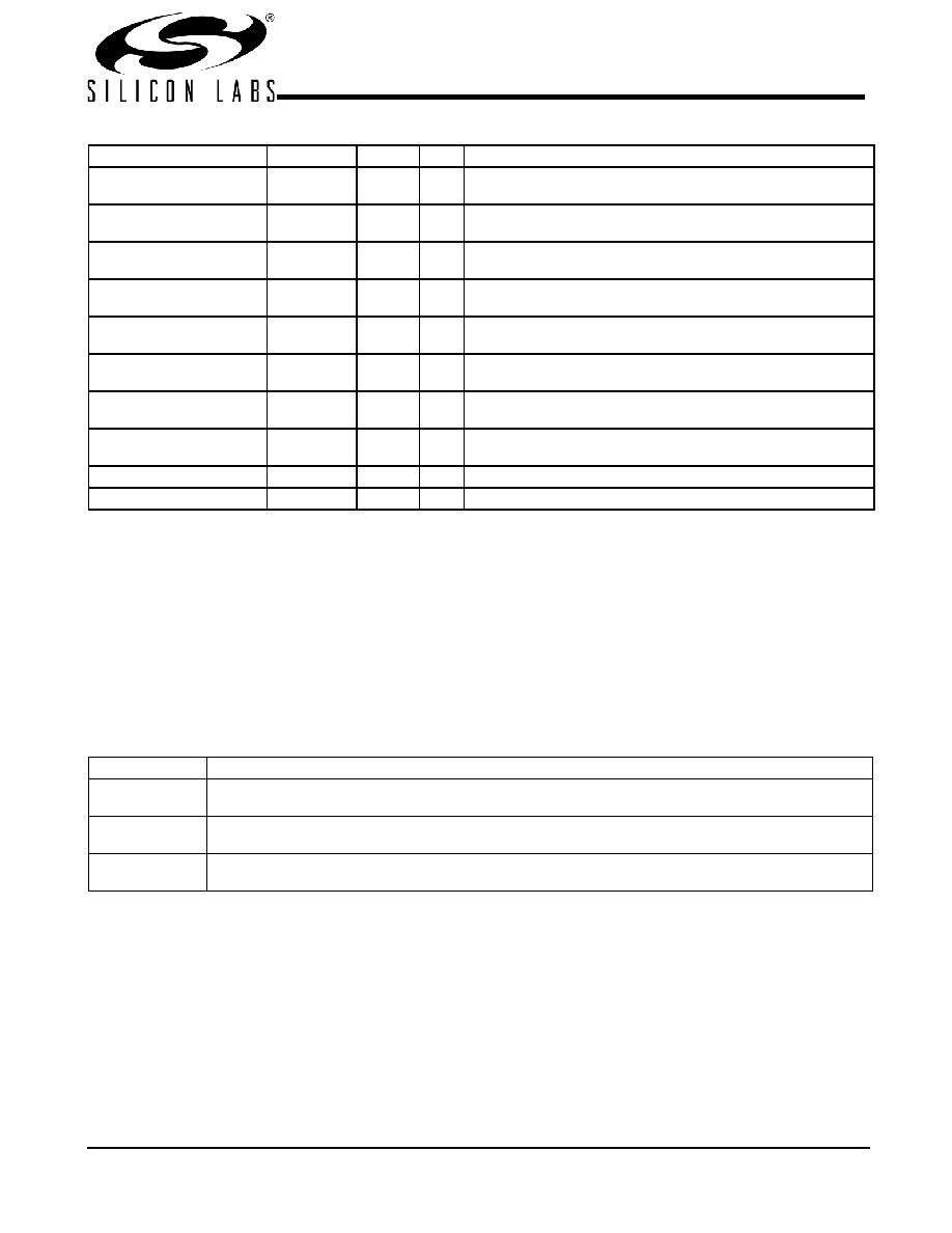
Pin Description
Pin
Name
PWR
I/O
Description
11, 13, 19, 21, 38, 36,
5, 7, 44, 42, 32, 30
DDRA[0:5]T
DDRB[0:5]T
VDD2.5
O
Clock outputs. These outputs provide copies of BUF_INA and
BUF_INB, respectively.
12, 14, 20, 22, 37, 35,
6, 8, 43, 41, 31, 29
DDRA[0:5]C
DDRB[0:5]C
VDD2.5
O
Clock outputs. These outputs provide complementary copies of
BUF_INA and BUF_INB, respectively.
18,
4
BUF_INA,
BUF_INB
VDD2.5
I
PD
Reference input from chipset. 2.5V input. Internal pull-down
17,
3
FB_OUTA
FB_OUTB
VDD2.5
O
Feedback clock for chipset.
45
I2C_CS
VDD2.5
I
PD
CS for I2C allows for multiple devices to be connected with
the same I2C address. Internal pull-down. See Table 1.
46
ADDR_SEL
VDD2.5
I
PD
Selects I2C Address D2/DC. Internal Pull-down
25
SCLK
VDD2.5
I
PU
SMBus clock input. Internal Pull-up
26
SDATA
VDD2.5
I/O
PU
SMBus data input. Internal Pull-up
1, 10, 16, 23, 28, 33, 39, 48 VDD2.5
2.5V voltage supply
2, 9, 15, 24, 27, 34, 40, 47
GND
Ground
Table 1. Command Code Definition
Bit
Description
7
0 = Block Read or Block Write operation
1 = Byte Read or Byte Write operation
(6:5)
01 to address chip when I2C_CS = 0
10 to address chip when I2C_CS = 1
(4:0)
Byte offset for Byte Read or Byte Write operation. For Block Read or Block Write operations, these bits should
be '00000'
相關(guān)PDF資料 |
PDF描述 |
|---|---|
| CY28378OXC | IC CLOCK CK408/TITAN 845 48SSOP |
| CY284108ZXC | IC CLOCK SERV CK410B 56TSSOP |
| CY28410OXC-2 | IC CLOCK CK410 GRANTSDALE 56SSOP |
| CY28410OXC | IC CLOCK CK410 GRANTSDALE 56SSOP |
| CY28411ZXC | IC CLOCK CK410M ALVISO 56TSSOP |
相關(guān)代理商/技術(shù)參數(shù) |
參數(shù)描述 |
|---|---|
| CY28354OXC-400T | 功能描述:時(shí)鐘緩沖器 273MHz Output Buffer for 4 DDR DIMMs RoHS:否 制造商:Texas Instruments 輸出端數(shù)量:5 最大輸入頻率:40 MHz 傳播延遲(最大值): 電源電壓-最大:3.45 V 電源電壓-最小:2.375 V 最大功率耗散: 最大工作溫度:+ 85 C 最小工作溫度:- 40 C 封裝 / 箱體:LLP-24 封裝:Reel |
| CY28358 | 制造商:SPECTRALINEAR 制造商全稱:SPECTRALINEAR 功能描述:200-MHz Differential Clock Buffer/Driver |
| CY28358OC | 制造商:SPECTRALINEAR 制造商全稱:SPECTRALINEAR 功能描述:200-MHz Differential Clock Buffer/Driver |
| CY28358OCT | 制造商:CYPRESS 制造商全稱:Cypress Semiconductor 功能描述:200-MHz Differential Clock Buffer/Driver |
| CY28359 | 制造商:SPECTRALINEAR 制造商全稱:SPECTRALINEAR 功能描述:273 MHz 6 Output Buffer for DDR400 DIMMS |
發(fā)布緊急采購(gòu),3分鐘左右您將得到回復(fù)。