- 您現(xiàn)在的位置:買賣IC網(wǎng) > PDF目錄374167 > CS5158GDR16 (ZF Electronics Corporation) CPU 5-Bit Synchronous Buck Controller PDF資料下載
參數(shù)資料
| 型號: | CS5158GDR16 |
| 廠商: | ZF Electronics Corporation |
| 英文描述: | CPU 5-Bit Synchronous Buck Controller |
| 中文描述: | CPU的5位同步降壓控制器 |
| 文件頁數(shù): | 12/14頁 |
| 文件大?。?/td> | 231K |
| 代理商: | CS5158GDR16 |
Applications Information: continued
C
12
A heatsink may be added to TO-220 components to reduce
their thermal impedance. A number of PC board layout
techniques such as thermal vias and additional copper foil
area can be used to improve the power handling capability
of surface mount components.
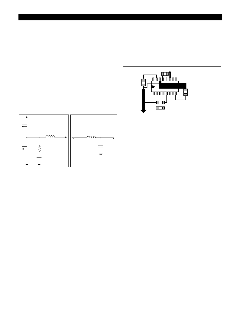
EMI Management
As a consequence of large currents being turned on and off
at high frequency, switching regulators generate noise as a
consequence of their normal operation. When designing for
compliance with EMI/EMC regulations, additional compo-
nents may be added to reduce noise emissions. These com-
ponents are not required for regulator operation and exper-
imental results may allow them to be eliminated. The input
filter inductor may not be required because bulk filter and
bypass capacitors, as well as other loads located on the
board will tend to reduce regulator di/dt effects on the cir-
cuit board and input power supply. Placement of the
power component to minimize routing distance will also
help to reduce emissions.
Figure 18: Filter components
Figure 19: Input Filter
Layout Guidelines
1. Place 12V filter capacitor next to the IC and connect
capacitor ground to pin 11 (PGnd).
2. Connect pin 11 (PGnd) with a separate trace to the
ground terminals of the 5V input capacitors.
3. Place fast feedback filter capacitor next to pin 8 (V
FFB
)
and connect it’s ground terminal with a separate, wide
trace directly to pin 14 (LGnd).
4. Connect the ground terminals of the Compensation
capacitor directly to the ground of the fast feedback filter
capacitor to prevent common mode noise from effecting
the PWM comparator.
5. Place the output filter capacitor(s) as close to the load as
possible and connect the ground terminal to pin 14 (LGnd).
6. Connect the V
FB
pin directly to the load with a separate
trace (remote sense).
7. Place 5V input capacitors close to the switching MOSFET
and synchronous MOSFET.
Route gate drive signals V
GATE(H)
(pin 10) and V
GATE(L)
(pin 12 when used) with traces that are a minimum of 0.025
inches wide.
Figure 20: Layout Guidelines
15
To the negative terminal of the
input capacitors
11
100pF
V
FFB
8
OFF TIME
5
SOFTSTART
V
CC
0.1
μ
F
To the negative terminal of the output capacitors
1.0
μ
F
V
COMP
+
2
μ
H
1200
μ
F x 3/16V
33
1000pF
2
μ
H
相關(guān)PDF資料 |
PDF描述 |
|---|---|
| CS5165GDW16 | Fast, Precise 5-Bit Synchronous Buck Controller for the Next Generation Low Voltage Pentium II Processors |
| CS5165GDWR16 | Fast, Precise 5-Bit Synchronous Buck Controller for the Next Generation Low Voltage Pentium II Processors |
| CS5165HGDW16 | Fast, Precise 5-Bit Synchronous Buck Controller for the Next Generation Low Voltage Pentium II Processors |
| CS5165 | Fast, Precise 5-Bit Synchronous Buck Controller for the Next Generation Low Voltage Pentium II Processors |
| CS5165H | Fast, Precise 5-Bit Synchronous Buck Controller for the Next Generation Low Voltage Pentium II Processors |
相關(guān)代理商/技術(shù)參數(shù) |
參數(shù)描述 |
|---|---|
| CS-516003 | 制造商:未知廠家 制造商全稱:未知廠家 功能描述:Analog Attenuator |
| CS5160GD | 制造商:Rochester Electronics LLC 功能描述:- Bulk |
| CS5160GD16 | 制造商:Rochester Electronics LLC 功能描述:- Bulk |
| CS5160GDR16 | 制造商:Rochester Electronics LLC 功能描述:- Bulk |
| CS5161GD16 | 制造商:ON Semiconductor 功能描述: |
發(fā)布緊急采購,3分鐘左右您將得到回復(fù)。