- 您現在的位置:買賣IC網 > PDF目錄374167 > CS5155GDR16 (ZF Electronics Corporation) CPU 5-Bit Synchronous Buck Controller PDF資料下載
參數資料
| 型號: | CS5155GDR16 |
| 廠商: | ZF Electronics Corporation |
| 英文描述: | CPU 5-Bit Synchronous Buck Controller |
| 中文描述: | CPU的5位同步降壓控制器 |
| 文件頁數: | 8/14頁 |
| 文件大?。?/td> | 279K |
| 代理商: | CS5155GDR16 |
Applications Information: continued
C
8
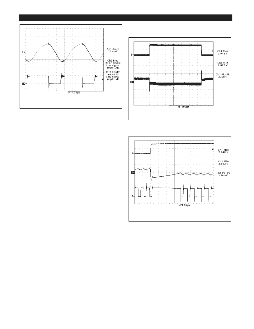
Figure 6: Peak-to-peak ripple on V
OUT
= 2.8V, I
OUT
= 13A (heavy load).
Transient Response
The CS5155 V
2
acontrol loops 100ns reaction time pro-
vides unprecedented transient response to changes in input
voltage or output current. Pulse by pulse adjustment of
duty cycle is provided to quickly ramp the inductor current
to the required level. Since the inductor current cannot be
changed instantaneously, regulation is maintained by the
output capacitor(s) during the time required to slew the
inductor current.
Overall load transient response is further improved
through a feature called òadaptive voltage positioningó.
This technique pre-positions the output capacitors voltage
to reduce total output voltage excursions during changes in
load.
Holding tolerance to 1% allows the error amplifiers refer-
ence voltage to be targeted +40mV high without compro-
mising DC accuracy. A òdroop resistorò, implemented
through a PC board trace, connects the error amplifiers
feedback pin (V
FB
) to the output capacitors and load and
carries the output current. With no load, there is no DC
drop across this resistor, producing an output voltage
tracking the error amplifiers, including the +40mV offset.
When the full load current is delivered, an 80mV drop is
developed across this resistor. This results in output volt-
age being offset -40mV low.
The result of adaptive voltage positioning is that additional
margin is provided for a load transient before reaching the
output voltage specification limits. When load current sud-
denly increases from its minimum level, the output capaci-
tor is pre-positioned +40mV. Conversely, when load cur-
rent suddenly decreases from its maximum level, the out-
put capacitor is pre-positioned -40mV (see Figures 7, 8, and
9). For best transient response, a combination of a number
of high frequency and bulk output capacitors are usually
used.
If the maximum on time is exceeded while responding to a
sudden increase in load current, a normal off time occurs to
prevent saturation of the output inductor.
Figure 7: CS5155 demonstration board response to a 0.5 to 13A load
pulse (output set for 2.8V).
Figure 8: CS5155 demonstration board response to 13A load turn on
(output set for 2.8V). Upon completing a normal off time, the V
2
acon-
trol loop immediately connects the inductor to the input voltage, pro-
viding 100% duty cycle. Regulation is achieved in less than 20μs.
Trace 1 - Regulator Output Voltage (1V/div.)
Trace 2 - Inductor Switching Node (5V/div.)
Trace 3 - Output Current (0.5 to 13 Amps) (20V/div.)
Trace 1 - Regulator Output Voltage (1V/div.)
Trace 3 - Regulator Output Current (20V/div.)
Trace1 - Regulator Output Voltage (10V/div.)
Trace 2 - Inductor Switching Node (5V/div.)
相關PDF資料 |
PDF描述 |
|---|---|
| CS5155HGD16 | CPU 5-Bit Synchronous Buck Controller |
| CS5155HGDR16 | CPU 5-Bit Synchronous Buck Controller |
| CS5155 | CPU 5-Bit Synchronous Buck Controller |
| CS5155H | CPU 5-Bit Synchronous Buck Controller |
| CS5155GD16 | CPU 5-Bit Synchronous Buck Controller |
相關代理商/技術參數 |
參數描述 |
|---|---|
| CS-5155HD16 | 制造商:未知廠家 制造商全稱:未知廠家 功能描述:Voltage-Mode SMPS Controller |
| CS-5155HDR16 | 制造商:未知廠家 制造商全稱:未知廠家 功能描述:Voltage-Mode SMPS Controller |
| CS-5155HN16 | 制造商:未知廠家 制造商全稱:未知廠家 功能描述:Voltage-Mode SMPS Controller |
| CS5155N16 | 制造商:ON Semiconductor 功能描述: |
| CS-5155N16 | 制造商:未知廠家 制造商全稱:未知廠家 功能描述:Voltage-Mode SMPS Controller |
發(fā)布緊急采購,3分鐘左右您將得到回復。