- 您現(xiàn)在的位置:買(mǎi)賣(mài)IC網(wǎng) > PDF目錄369655 > CAT34RC02SP2ITE13REV-E The CAT24FC02 is a 2-kb Serial CMOS EEPROM internally organized as 256 words of 8 bits each PDF資料下載
參數(shù)資料
| 型號(hào): | CAT34RC02SP2ITE13REV-E |
| 元件分類(lèi): | EEPROM |
| 英文描述: | The CAT24FC02 is a 2-kb Serial CMOS EEPROM internally organized as 256 words of 8 bits each |
| 中文描述: | 該CAT24FC02是一個(gè)2 KB的EEPROM的國(guó)內(nèi)256個(gè)8位每字舉辦的串行CMOS |
| 文件頁(yè)數(shù): | 3/16頁(yè) |
| 文件大小: | 445K |
| 代理商: | CAT34RC02SP2ITE13REV-E |
第1頁(yè)第2頁(yè)當(dāng)前第3頁(yè)第4頁(yè)第5頁(yè)第6頁(yè)第7頁(yè)第8頁(yè)第9頁(yè)第10頁(yè)第11頁(yè)第12頁(yè)第13頁(yè)第14頁(yè)第15頁(yè)第16頁(yè)
CAT34RC02
3
Doc No. 1052, Rev. K
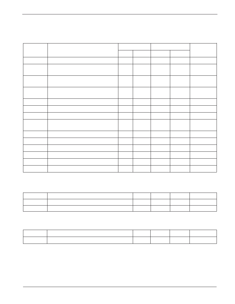
Write Cycle Limits
Symbol
Parameter
Min
Typ
Max
Units
t
WR
Write Cycle Time
5
ms
A.C. CHARACTERISTICS
V
CC
= 1.7 V to 5.5 V, unless otherwise specified.
Read & Write Cycle Limits
Symbol
Parameter
1.7 V - 5.5 V
2.5 V - 5.5 V
Min
Max
Min
Max
Units
F
SCL
T
I(1)
Clock Frequency
100
400
kHz
Noise Suppression Time
Constant at SCL, SDA Inputs
100
100
ns
t
AA
SCL Low to SDA Data Out
and ACK Out
3.5
0.9
μ
s
t
BUF(1)
Time the Bus Must be Free Before
a New Transmission Can Start
4.7
1.3
μ
s
t
HD:STA
Start Condition Hold Time
4
0.6
μ
s
μ
s
μ
s
μ
s
t
LOW
Clock Low Period
4.7
1.3
t
HIGH
Clock High Period
4
0.6
t
SU:STA
Start Condition Setup Time
(for a Repeated Start Condition)
4.7
0.6
t
HD:DAT
Data In Hold Time
0
0
ns
t
SU:DAT
t
R(1)
t
F(1)
Data In Setup Time
250
100
ns
SDA and SCL Rise Time
1
0.3
μ
s
SDA and SCL Fall Time
300
300
ns
t
SU:STO
Stop Condition Setup Time
4
0.6
μ
s
t
DH
Data Out Hold Time
100
100
ns
Note:
(1) This parameter is tested initially and after a design or process change that affects the parameter.
(2) t
PUR
and t
PUW
are the delays required from the time V
CC
is stable until the specified operation can be initiated.
Power-Up Timing
(1)(2)
Symbol
Parameter
Min
Typ
Max
Units
t
PUR
t
PUW
Power-up to Read Operation
Power-up to Write Operation
1
1
ms
ms
The write cycle time is the time elapsed between the
STOP command (following the write instruction) and the
completion of the internal write cycle. During the internal
write cycle, SDA is released by the Slave and the device
does not acknowledge external commands.
相關(guān)PDF資料 |
PDF描述 |
|---|---|
| CAT34RC02UETE13REV-E | The CAT24FC02 is a 2-kb Serial CMOS EEPROM internally organized as 256 words of 8 bits each |
| CAT34RC02UITE13REV-E | The CAT24FC02 is a 2-kb Serial CMOS EEPROM internally organized as 256 words of 8 bits each |
| CAT34RC02VP2ETE13REV-E | The CAT24FC02 is a 2-kb Serial CMOS EEPROM internally organized as 256 words of 8 bits each |
| CAT34RC02VP2ITE13REV-E | The CAT24FC02 is a 2-kb Serial CMOS EEPROM internally organized as 256 words of 8 bits each |
| CAT34RC02WETE13REV-E | The CAT24FC02 is a 2-kb Serial CMOS EEPROM internally organized as 256 words of 8 bits each |
相關(guān)代理商/技術(shù)參數(shù) |
參數(shù)描述 |
|---|---|
| CAT34RC02UETE13REV-E | 制造商:CATALYST 制造商全稱(chēng):Catalyst Semiconductor 功能描述:2-kb I2C Serial EEPROM, Serial Presence Detect |
| CAT34RC02UITE13 | 制造商:CATALYST 制造商全稱(chēng):Catalyst Semiconductor 功能描述:2-kb I2C Serial EEPROM, Serial Presence Detect |
| CAT34RC02UITE13REV-E | 制造商:CATALYST 制造商全稱(chēng):Catalyst Semiconductor 功能描述:2-kb I2C Serial EEPROM, Serial Presence Detect |
| CAT34RC02VP2ETE13REV-E | 制造商:CATALYST 制造商全稱(chēng):Catalyst Semiconductor 功能描述:2-kb I2C Serial EEPROM, Serial Presence Detect |
| CAT34RC02VP2GI-T3 | 制造商:Rochester Electronics LLC 功能描述: 制造商:Catalyst Semiconductor 功能描述: |
發(fā)布緊急采購(gòu),3分鐘左右您將得到回復(fù)。