- 您現(xiàn)在的位置:買賣IC網(wǎng) > PDF目錄375534 > C1206N56931G4C (KEMET Corporation) CERAMIC CHIP CAPACITORS PDF資料下載
參數(shù)資料
| 型號: | C1206N56931G4C |
| 廠商: | KEMET Corporation |
| 英文描述: | CERAMIC CHIP CAPACITORS |
| 中文描述: | 陶瓷芯片電容器 |
| 文件頁數(shù): | 2/30頁 |
| 文件大?。?/td> | 2058K |
| 代理商: | C1206N56931G4C |
第1頁當(dāng)前第2頁第3頁第4頁第5頁第6頁第7頁第8頁第9頁第10頁第11頁第12頁第13頁第14頁第15頁第16頁第17頁第18頁第19頁第20頁第21頁第22頁第23頁第24頁第25頁第26頁第27頁第28頁第29頁第30頁
KEMET Electronics Corporation, P.O. Box 5928, Greenville, S.C. 29606, (864) 963-6300
CERAMIC CHIP CAPACITORS
5.
Dissipation Factor:
Measured under same conditions as
capacitance. (See Table 3)
Dissipation factor (DF) is a measure of the losses in
a capacitor under AC application. It is the ratio of the
equivalent series resistance to the capacitive reac-
tance, and is usually expressed in percent. It is normal-
ly measured simultaneously with capacitance, and
under the same conditions. The vector diagram below
illustrates the relationship between DF, ESR and
impedance. The reciprocal of the dissipation factor is
called the
“
Q
”
or quality factor. For convenience, the
“
Q
”
factor is often used for very low values of dissipa-
tion factor especially when measured at high frequen-
cies. DF is sometimes called the
“
loss tangent
”
or
“
tan-
gent
”
, as shown in Figure 2.
6.
Impedance:
Since the parallel resistance (IR) is normally very
high, the total impedance of the capacitor can be
approximated by:
Figure 3
The variation of a capacitor's impedance with fre-
quency determines its effectiveness in many applica-
tions. At high frequency more detailed models apply -
see KEMET SPICE models for such instances.
7.
Insulation Resistance:
Measured after 2 minutes electrification at 25°C and
rated voltage: Limits per Table 3.
Insulation Resistance is the measure of a capacitor
to resist the flow of DC leakage current. It is sometimes
referred to as
“
leakage resistance
”
. Insulation resis-
tance (IR) is the DC resistance measured across the
terminals of a capacitor, represented by the parallel
resistance (IR) shown in Figure 1. For a given dielectric
type, electrode area increases with capacitance, result-
ing in a decrease in the insulation resistance.
Consequently, insulation resistance limits are usually
specified as the
“
RC
”
(IR x C) product, in terms of ohm-
farads or megohm-micro-farads. The insulation resis-
tance for a specific capacitance value is determined by
dividing this product by the capacitance. However, as
the nominal capacitance values become small, the
insulation resistance calculated from the RC product
reaches values which are impractical. Consequently, IR
specifications usually include both a minimum RC prod-
uct and a maximum limit based on the IR calculated
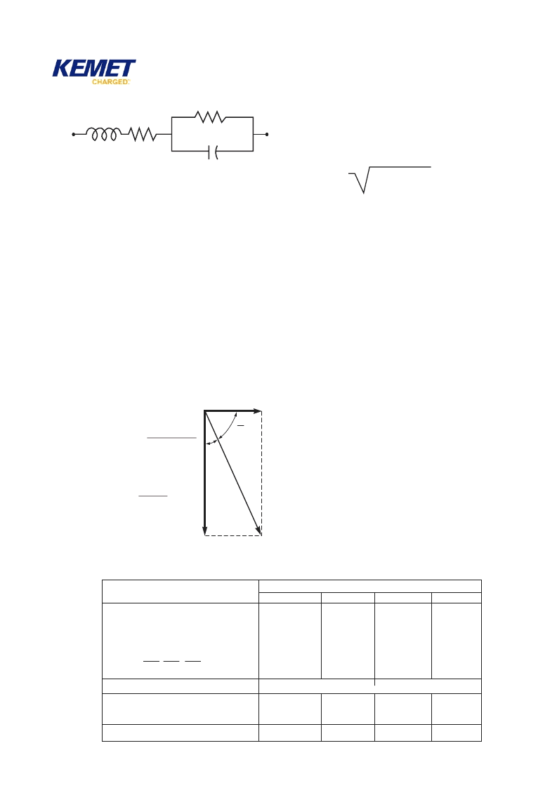
Figure 1
C = Capacitance
IR
ESR
C
ESL
ESL = Equivalent Series Inductance
IR = Insulation Resistance
ESR = Equivalent Series Resistance
ESR x 100
Xc
DF(%) =
Xc
2 π
fC
1
=
Figure 2
δ
Ζ
O
Xc
ESR
Z =
ESR + (XL - XC)
2
Where :
Z = Total Impedance
ESR = Equivalent Series Resistance
XC = Capacitive Reactance = 1/(2
π
fC)
XL = Inductive Reactance = (2
π
f
)
(ESL)
Table 3
–
Specified Electrical Limits
Parameter
Temperature Characteristics
X7R/X5R
C0G
Z5U
Capacitance & Dissipation Factor: Measured at following
conditions:
C0G – 1kHz and 1 vrms if capacitance >1000 pF
1MHz and 1 vrms if capacitance
≤
1000 pF
X7R/X5R/Y5V – 1kHz and 1 vrms* if capacitance
≤
10
μ
F
X7R/X5R/Y5V – 120Hz and 0.5 vrms if capacitance
>
10
μ
F
Y5V
Z5U – 1kHz and 0.5 vrms
DF Limits:
**X5R
<25V
<25V
50 - 200 volts –
25 volts –
16 volts –
6.3/10 volts –
Dielectric Strength: At 2.5 times rated DC voltage
Insulation Resistance (IR): At rated DC voltage, whichever
of the two is smaller. To get IR limit, divide M
F
value by
the capacitance and compare to G
limit. Select the lower
of the two limits.
Temperature: Range,
°
C
Capacitance Change (without DC voltage)
0.10%
0.10%
--------
--------
2.5%
3.5%
3.5%
5.0%
2.5%
5.0%
**
**
Pass Subsequent IR Test
1,000 M
–
μ
F
or 100 G
(100,000 M
)
1,000 M
–
μ
F
or 100 G
(100,000 M
)
100 M
–
μ
F
or 10 G
(10,000 M
)
-55 to +125
0
±
30 ppm/
°
C
-55 to +125
±
15%
-55 to +85
±
15%
+10 to +85
+22% -56%
5.0%
7.0%
7.0%
10.0%
100 M
–
μ
F
or 10 G (
≥
16 volt)
50 M
–
F
or 10G (
≤
10v)
(10,000 M
)
-30 to +85
+22% -82%
4.0%
4.0%
-------
X7R:
X5R:
Cap
<564
≥
564
DF
5.0%
10.0%
*Note: Some values measured at
1
2
volt, see X7R Table for specific details on pages 7
4
and 7
5
.
6
8
相關(guān)PDF資料 |
PDF描述 |
|---|---|
| C1206N62031G4C | CERAMIC CHIP CAPACITORS |
| C1206X102M4RAC | Surface Mount Ceramic Chip Capacitors / FT-CAP / Flexible Terminations |
| C1206X102J1RAC | Surface Mount Ceramic Chip Capacitors / FT-CAP / Flexible Terminations |
| C1206X102J2RAC | Surface Mount Ceramic Chip Capacitors / FT-CAP / Flexible Terminations |
| C1206X102J3RAC | Surface Mount Ceramic Chip Capacitors / FT-CAP / Flexible Terminations |
相關(guān)代理商/技術(shù)參數(shù) |
參數(shù)描述 |
|---|---|
| C1206N569B1GRC | 功能描述:多層陶瓷電容器MLCC - SMD/SMT 5.60PF 100V RoHS:否 制造商:American Technical Ceramics (ATC) 電容:10 pF 容差:1 % 電壓額定值:250 V 溫度系數(shù)/代碼:C0G (NP0) 外殼代碼 - in:0505 外殼代碼 - mm:1414 工作溫度范圍:- 55 C to + 125 C 產(chǎn)品:Low ESR MLCCs 封裝:Reel |
| C1206N569B1GRH | 功能描述:多層陶瓷電容器MLCC - SMD/SMT 5.60PF 100V RoHS:否 制造商:American Technical Ceramics (ATC) 電容:10 pF 容差:1 % 電壓額定值:250 V 溫度系數(shù)/代碼:C0G (NP0) 外殼代碼 - in:0505 外殼代碼 - mm:1414 工作溫度范圍:- 55 C to + 125 C 產(chǎn)品:Low ESR MLCCs 封裝:Reel |
| C1206N569B1GRHTM | 制造商:KEMET Corporation 功能描述:CAP 5.6PF 100VDC C0G 0.1PF SMD 1206 0.01% - Tape and Reel |
| C1206N569B1GRL | 功能描述:多層陶瓷電容器MLCC - SMD/SMT 5.60PF 100V RoHS:否 制造商:American Technical Ceramics (ATC) 電容:10 pF 容差:1 % 電壓額定值:250 V 溫度系數(shù)/代碼:C0G (NP0) 外殼代碼 - in:0505 外殼代碼 - mm:1414 工作溫度范圍:- 55 C to + 125 C 產(chǎn)品:Low ESR MLCCs 封裝:Reel |
| C1206N569B1GSC | 功能描述:多層陶瓷電容器MLCC - SMD/SMT 5.60PF 100V RoHS:否 制造商:American Technical Ceramics (ATC) 電容:10 pF 容差:1 % 電壓額定值:250 V 溫度系數(shù)/代碼:C0G (NP0) 外殼代碼 - in:0505 外殼代碼 - mm:1414 工作溫度范圍:- 55 C to + 125 C 產(chǎn)品:Low ESR MLCCs 封裝:Reel |
發(fā)布緊急采購,3分鐘左右您將得到回復(fù)。