- 您現(xiàn)在的位置:買賣IC網(wǎng) > PDF目錄369515 > BT169 (友順科技股份有限公司) SCR PDF資料下載
參數(shù)資料
| 型號: | BT169 |
| 廠商: | 友順科技股份有限公司 |
| 英文描述: | SCR |
| 中文描述: | 可控硅 |
| 文件頁數(shù): | 3/7頁 |
| 文件大小: | 52K |
| 代理商: | BT169 |
Philips Semiconductors
Product specification
Thyristor
logic level
BT169W Series
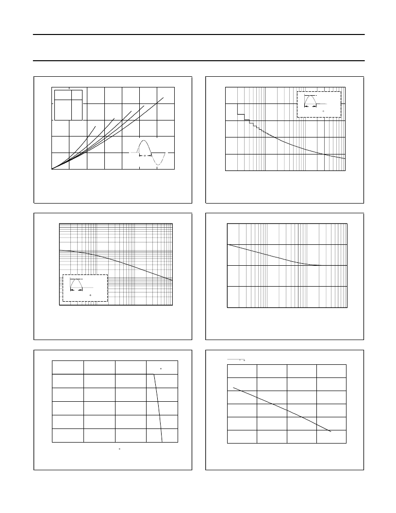
Fig.1. Maximum on-state dissipation, P
, versus
average on-state current, I
T(AV)
, where a = form
factor = I
T(RMS)
T(AV)
.
Fig.2. Maximum permissible non-repetitive peak
on-state current I
, versus pulse width t
p
, for
sinusoidal currents, t
p
≤
10ms.
Fig.3. Maximum permissible rms current I
T(RMS)
,
versus solder point temperature T
sp
.
Fig.4. Maximum permissible non-repetitive peak
on-state current I
, versus number of cycles, for
sinusoidal currents, f = 50 Hz.
Fig.5. Maximum permissible repetitive rms on-state
current I
T(RMS)
, versus surge duration, for sinusoidal
sp
≤
112C.
Fig.6. Normalised gate trigger voltage
V
GT
(T
j
)/ V
GT
(25C), versus junction temperature T
j
.
0
0.1
0.2
0.3
0.4
0.5
0.6
0.7
0
0.2
0.4
0.6
0.8
1
a = 1.57
1.9
2.2
2.8
4
BT169W
IF(AV) / A
Ptot / W
125
122
119
116
113
110
Tsp(max) / C
conduction
30
60
90
120
180
form
a
4
2.8
2.2
1.9
1.57
1
10
100
1000
0
2
4
6
8
10
BT169
Number of half cycles at 50Hz
ITSM / A
T
ITSM
time
I
Tj initial = 25 C max
T
1
10
100
1000
BT169
100us
1ms
10ms
T / s
ITSM / A
T
ITSM
time
I
Tj initial = 25 C max
T
0
0.1
1
10
0.5
1
1.5
2
BT134W
surge duration / s
IT(RMS) / A
-50
0
50
100
150
0
0.2
0.4
0.6
0.8
1
1.2
BT134W
Tsp / C
IT(RMS) / A
112 C
-50
0
50
100
150
0.4
0.6
0.8
1
1.2
1.4
1.6
BT151
Tj / C
VGT(Tj)
VGT(25 C)
September 1997
3
Rev 1.200
相關(guān)PDF資料 |
PDF描述 |
|---|---|
| BT2-25T | |
| BT2-15 | |
| BT2-15T | |
| BT2-15TC | |
| BT2-25 | |
相關(guān)代理商/技術(shù)參數(shù) |
參數(shù)描述 |
|---|---|
| BT169_08 | 制造商:UTC-IC 制造商全稱:UTC-IC 功能描述:SCRS |
| BT169_SERIES | 制造商:未知廠家 制造商全稱:未知廠家 功能描述:Thyristors logic level |
| BT16952DGG | 制造商:PHILIPS 制造商全稱:NXP Semiconductors 功能描述:16-bit registered transceiver 3-State |
| BT16952DL | 制造商:PHILIPS 制造商全稱:NXP Semiconductors 功能描述:16-bit registered transceiver 3-State |
| BT169B | 制造商:NXP Semiconductors 功能描述:Thyristor SCR 200V 9A 3-Pin SPT |
發(fā)布緊急采購,3分鐘左右您將得到回復(fù)。