- 您現(xiàn)在的位置:買賣IC網(wǎng) > PDF目錄369509 > BT136-800F 8-Bit Multi-Level Pipeline Register 24-PDIP -40 to 85 PDF資料下載
參數(shù)資料
| 型號: | BT136-800F |
| 英文描述: | 8-Bit Multi-Level Pipeline Register 24-PDIP -40 to 85 |
| 中文描述: | 晶閘管產(chǎn)品目錄 |
| 文件頁數(shù): | 128/224頁 |
| 文件大小: | 2697K |
| 代理商: | BT136-800F |
第1頁第2頁第3頁第4頁第5頁第6頁第7頁第8頁第9頁第10頁第11頁第12頁第13頁第14頁第15頁第16頁第17頁第18頁第19頁第20頁第21頁第22頁第23頁第24頁第25頁第26頁第27頁第28頁第29頁第30頁第31頁第32頁第33頁第34頁第35頁第36頁第37頁第38頁第39頁第40頁第41頁第42頁第43頁第44頁第45頁第46頁第47頁第48頁第49頁第50頁第51頁第52頁第53頁第54頁第55頁第56頁第57頁第58頁第59頁第60頁第61頁第62頁第63頁第64頁第65頁第66頁第67頁第68頁第69頁第70頁第71頁第72頁第73頁第74頁第75頁第76頁第77頁第78頁第79頁第80頁第81頁第82頁第83頁第84頁第85頁第86頁第87頁第88頁第89頁第90頁第91頁第92頁第93頁第94頁第95頁第96頁第97頁第98頁第99頁第100頁第101頁第102頁第103頁第104頁第105頁第106頁第107頁第108頁第109頁第110頁第111頁第112頁第113頁第114頁第115頁第116頁第117頁第118頁第119頁第120頁第121頁第122頁第123頁第124頁第125頁第126頁第127頁當前第128頁第129頁第130頁第131頁第132頁第133頁第134頁第135頁第136頁第137頁第138頁第139頁第140頁第141頁第142頁第143頁第144頁第145頁第146頁第147頁第148頁第149頁第150頁第151頁第152頁第153頁第154頁第155頁第156頁第157頁第158頁第159頁第160頁第161頁第162頁第163頁第164頁第165頁第166頁第167頁第168頁第169頁第170頁第171頁第172頁第173頁第174頁第175頁第176頁第177頁第178頁第179頁第180頁第181頁第182頁第183頁第184頁第185頁第186頁第187頁第188頁第189頁第190頁第191頁第192頁第193頁第194頁第195頁第196頁第197頁第198頁第199頁第200頁第201頁第202頁第203頁第204頁第205頁第206頁第207頁第208頁第209頁第210頁第211頁第212頁第213頁第214頁第215頁第216頁第217頁第218頁第219頁第220頁第221頁第222頁第223頁第224頁

AN1002
Application Notes
http://www.teccor.com
+1 972-580-7777
AN1002 - 2
2002 Teccor Electronics
Thyristor Product Catalog
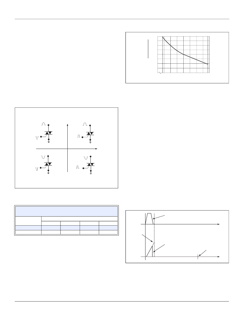
Triacs can be gated on in one of four basic gating modes as
shown in Figure AN1002.3. The most common quadrants for
gating on triacs are Quadrants I and III, where the gate supply is
synchronized with the main terminal supply (gate positive — MT2
positive, gate negative — MT2 negative). Optimum triac gate
sensitivity is achieved when operating in Quadrants I and III due
to the inherent thyristor chip construction. If Quadrants I and III
cannot be used, the next best operating modes are Quadrants II
and III where the gate supply has a negative polarity with an AC
main terminal supply. Typically, Quadrant II is approximately
equal in gate sensitivity to Quadrant I; however, latching current
sensitivity in Quadrant II is lowest. Therefore, it is difficult for
triacs to latch on in Quadrant II when the main terminal current
supply is very low in value.
Special consideration should be given to gating circuit design
when Quadrants I and IV are used in actual application, because
Quadrant IV has the lowest gate sensitivity of all four operating
quadrants.
Figure AN1002.3
Definition of Operating Quadrants in Triacs
The following table shows the relationships between different
gating modes in current required to gate on triacs.
Example of 4 A triac:
If I
GT
(I) = 10 mA, then
I
GT
(II) = 16 mA
I
GT
(III) = 25 mA
I
GT
(IV) = 27 mA
Gate trigger current is temperature-dependent as shown in
Figure AN1002.4. Thyristors become less sensitive with
decreasing temperature and more sensitive with increasing
temperature.
Figure AN1002.4
Typical DC Gate Trigger Current versus Case
Temperature
For applications where low temperatures are expected, gate cur-
rent supply should be increased to at least two to eight times the
gate trigger current requirements at 25
°
C. The actual factor var-
ies by thyristor type and the environmental temperature.
Example of a 10 A triac:
If I
GT
(I) = 10 mA at 25 °C, then
I
GT
(I) = 20 mA at -40 °C
In applications where high di/dt, high surge, and fast turn-on are
expected, gate drive current should be steep rising (1 μs rise
time) and at least twice rated I
GT
or higher with minimum 3 μs
pulse duration. However, if gate drive current magnitude is very
high, then duration may have to be limited to keep from over-
stressing (exceeding the power dissipation limit of) gate junction.
Latching Current of SCRs and Triacs
Latching current (I
) is the minimum principal current required to
maintain the thyristor in the on state immediately after the switch-
ing from off state to on state has occurred and the triggering sig-
nal has been removed. Latching current can best be understood
by relating to the “pick-up” or “pull-in” level of a mechanical relay.
Figure AN1002.5 and Figure AN1002.6 illustrate typical thyristor
latching phenomenon.
In the illustrations in Figure AN1002.5, the thyristor does not stay
on after gate drive is removed due to insufficient available princi-
pal current (which is lower than the latching current requirement).
Figure AN1002.5
Latching Characteristic of Thyristor (Device Not
Latched)
In the illustration in Figure AN1002.6 the device stays on for the
remainder of the half cycle until the principal current falls below
the holding current level. Figure AN1002.5 shows the character-
istics of the same device if gate drive is removed or shortened
before latching current requirement has been met.
Typical Ratio of
at 25 °C
Type
4 A Triac
10 A Triac
Operating Mode
Quadrant II
1.6
Quadrant I
1
Quadrant III
2.5
Quadrant IV
2.7
1
1.5
1.4
3.1
MT2 POSITIVE
(Positive Half Cycle)
MT2 NEGATIVE
(Negative Half Cycle)
MT1
MT2
+
I
GT
REF
QII
QIII
MT1
I
GATE
MT2
REF
MT1
MT2
REF
MT1
MT2
REF
QI
QIV
ALL POLARITIES ARE REFERENCED TO MT1
(
-
)
I
GATE
(+)
I
GT
-
I
GATE
(
-
)
I
GATE
(+)
NOTE: Alternistors will not operate in Q IV
)
)
IGTIGTQuadrant 1
2.0
1.5
1.0
.5
0
-40
-15
+25
+65
+100
Case Temperature (TC) – C
R
I
I
Gate Pulse
(Gate Drive to Thyristor)
Principal
Current
Through
Thyristor
Latching
Current
Requirement
Time
Zero
Crossing Point
Time
相關(guān)PDF資料 |
PDF描述 |
|---|---|
| BT136S | Triacs |
| BT136_SERIES | Transient Voltage Suppressor Diodes |
| BT136_SERIES_D | Transient Voltage Suppressor Diodes |
| BT136_SERIES_E | Transient Voltage Suppressor Diodes |
| BT136F700 | Transient Voltage Suppressor Diodes |
相關(guān)代理商/技術(shù)參數(shù) |
參數(shù)描述 |
|---|---|
| BT136-800G | 制造商:TECCOR 制造商全稱:TECCOR 功能描述:Thyristor Product Catalog |
| BT136B | 制造商:PHILIPS 制造商全稱:NXP Semiconductors 功能描述:Triacs sensitive gate |
| BT136B_SERIES_E | 制造商:未知廠家 制造商全稱:未知廠家 功能描述:Triacs sensitive gate |
| BT136B-500 | 制造商:PHILIPS 制造商全稱:NXP Semiconductors 功能描述:Triacs |
| BT136B-500D | 制造商:PHILIPS 制造商全稱:NXP Semiconductors 功能描述:Triacs logic level |
發(fā)布緊急采購,3分鐘左右您將得到回復。