- 您現(xiàn)在的位置:買賣IC網(wǎng) > PDF目錄369509 > BT136-600D Thyristor Product Catalog PDF資料下載
參數(shù)資料
| 型號(hào): | BT136-600D |
| 英文描述: | Thyristor Product Catalog |
| 中文描述: | 晶閘管產(chǎn)品目錄 |
| 文件頁數(shù): | 162/224頁 |
| 文件大?。?/td> | 2697K |
| 代理商: | BT136-600D |
第1頁第2頁第3頁第4頁第5頁第6頁第7頁第8頁第9頁第10頁第11頁第12頁第13頁第14頁第15頁第16頁第17頁第18頁第19頁第20頁第21頁第22頁第23頁第24頁第25頁第26頁第27頁第28頁第29頁第30頁第31頁第32頁第33頁第34頁第35頁第36頁第37頁第38頁第39頁第40頁第41頁第42頁第43頁第44頁第45頁第46頁第47頁第48頁第49頁第50頁第51頁第52頁第53頁第54頁第55頁第56頁第57頁第58頁第59頁第60頁第61頁第62頁第63頁第64頁第65頁第66頁第67頁第68頁第69頁第70頁第71頁第72頁第73頁第74頁第75頁第76頁第77頁第78頁第79頁第80頁第81頁第82頁第83頁第84頁第85頁第86頁第87頁第88頁第89頁第90頁第91頁第92頁第93頁第94頁第95頁第96頁第97頁第98頁第99頁第100頁第101頁第102頁第103頁第104頁第105頁第106頁第107頁第108頁第109頁第110頁第111頁第112頁第113頁第114頁第115頁第116頁第117頁第118頁第119頁第120頁第121頁第122頁第123頁第124頁第125頁第126頁第127頁第128頁第129頁第130頁第131頁第132頁第133頁第134頁第135頁第136頁第137頁第138頁第139頁第140頁第141頁第142頁第143頁第144頁第145頁第146頁第147頁第148頁第149頁第150頁第151頁第152頁第153頁第154頁第155頁第156頁第157頁第158頁第159頁第160頁第161頁當(dāng)前第162頁第163頁第164頁第165頁第166頁第167頁第168頁第169頁第170頁第171頁第172頁第173頁第174頁第175頁第176頁第177頁第178頁第179頁第180頁第181頁第182頁第183頁第184頁第185頁第186頁第187頁第188頁第189頁第190頁第191頁第192頁第193頁第194頁第195頁第196頁第197頁第198頁第199頁第200頁第201頁第202頁第203頁第204頁第205頁第206頁第207頁第208頁第209頁第210頁第211頁第212頁第213頁第214頁第215頁第216頁第217頁第218頁第219頁第220頁第221頁第222頁第223頁第224頁

AN1006
Application Notes
http://www.teccor.com
+1 972-580-7777
AN1006 - 10
2002 Teccor Electronics
Thyristor Product Catalog
Procedure 12: I
GT
– Quadrant II [MT2 (+) Gate (-)]
To measure the I
GT
– Quadrant II parameter:
1. Set
Step/Offside Polarity
by depressing Invert (release but-
ton on 577).
2. Set
Polarity
to (+).
3. Set observed dot to bottom right corner of CRT grid by turn-
ing the horizontal position knob. When Quadrant II testing is
complete, return dot to original position.
4. Repeat Procedure 11.
Procedure 13: I
GT
– Quadrant III [MT2 (-) Gate (-)]
To measure the I
GT
– Quadrant III parameter:
1. Set
Polarity
to (–).
2. Set
Step/Offset Polarity
to non-inverted position (button
extended, on 577 button depressed).
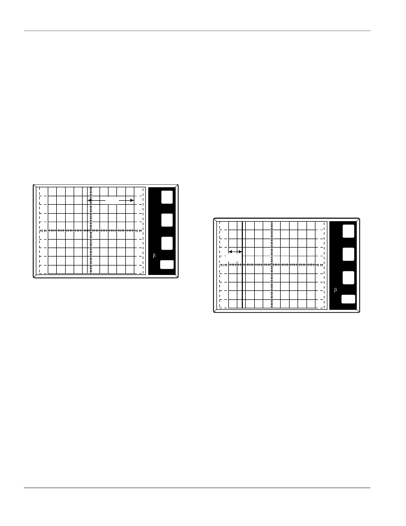
3. Repeat Procedure 11. (Figure AN1006.15)
Figure AN1006.15 I
GT
in Quadrant III = 27 mA
Procedure 14: I
GT
– Quadrant IV [MT2 (-) Gate (+)]
To measure the I
GT
– Quadrant IV parameter:
1. Set
Polarity
to (–).
2. Set
Step/Offset Polarity
by depressing
Invert
(release but-
ton on 577).
3. Set observed dot to top left corner of CRT grid by turning the
Horizontal
position knob. When Quadrant IV testing is com-
plete, return dot to original position.
4. Repeat Procedure 11.
Procedure 15: V
GT
To measure the V
GT
parameter:
1. Set
Polarity
to (+).
2. Set
Number of Steps
to
1
. (Set steps to
0
(zero) on 370.)
3. Set
Offset
by depressing
Aid.
(On 577, also set
0
(zero) but-
ton to
Offset
. Button is extended.)
4. Set
Offset Multiplier
to
0
(zero). (Press
Aid
and O
ppose
at
same time on 370.)
5. Set
Terminal Selector
to
Step Generator-Emitter Grounded
.
6. Set
Mode
to
Norm
.
7. Set
Max Peak Volts
to
15 V
. (
16 V
on 370)
8. Set
Power Dissipation
to
10 W
.
9. Set
Step Family
by depressing
Single
.
10. Set
Horizontal
knob to
2 V/DIV
.
11. Set
Step/Offset Polarity
to non-inverted position (button
extended, on 577 button depressed).
12. Set
Current Limit
to 500 mA (not available on 577).
13. Increase
Variable Collector Supply Voltage
until voltage
reaches 12 V on CRT.
14. After 12 V setting is complete, change
Horizontal
knob to
Step Generator.
Procedure 16: V
GT
– Quadrant I [MT2 (+) Gate (+)]
To measure the V
GT
– Quadrant I parameter:
1. Set
Step/Offset Amplitude
to 20% of rated V
GT
.
2. Set
Left-Right Terminal Jack Selector
to correspond with
location of test fixture.
3. Gradually increase
Offset Multiplier
until device reaches
conduction point. (Figure AN1006.16) Measure V
GT
by fol-
lowing horizontal axis to the point where the vertical line
passes through the axis. This measured value will be V
GT
.
(On 370, V
GT
will be numerically displayed on screen under
offset value.)
Figure AN1006.16 V
GT
in Quadrant I = 780 mV
Procedure 17: V
GT
– Quadrant II [MT2 (+) Gate (-)]
To measure the V
GT
– Quadrant II parameter:
1. Set
Step/Offset Polarity
by depressing
Invert
(release but-
ton on 577).
2. Set
Polarity
to (+).
3. Set observed dot to bottom right corner of CRT grid by turn-
ing the horizontal position knob. When Quadrant II testing is
complete, return dot to original position.
4. Repeat Procedure 16.
Procedure 18: V
GT
– Quadrant III [MT2 (-) Gate (-)]
To measure the V
GT
– Quadrant III parameter:
1. Set
Polarity
to (–).
2. Set
Step/Offset Polarity
to non-inverted position (button
extended, on 577 button depressed).
50
mA
10
PER
V
E
R
T
DIV
PER
H
O
R
I
Z
DIV
PER
S
T
E
P
()k
DIV
9m
PER
DIV
5
mA
IGT
50
mA
500
mV
PER
V
E
R
T
DIV
PER
H
O
R
I
Z
DIV
PER
S
T
E
P
()k
DIV
9m
PER
DIV
100m
VGT
相關(guān)PDF資料 |
PDF描述 |
|---|---|
| BT136-600E | High Performance 1:10 Clock Buffer for General Purpose Applications 24-TSSOP -40 to 85 |
| BT136-600F | High Performance 1:10 Clock Buffer for General Purpose Applications 24-TSSOP -40 to 85 |
| BT136-600G | CompactFlash Bus-interface Chip 114-BGA MICROSTAR -40 to 85 |
| BT136-800F | 8-Bit Multi-Level Pipeline Register 24-PDIP -40 to 85 |
| BT136S | Triacs |
相關(guān)代理商/技術(shù)參數(shù) |
參數(shù)描述 |
|---|---|
| BT136-600D,127 | 功能描述:雙向可控硅 RAIL TRIAC RoHS:否 制造商:STMicroelectronics 開啟狀態(tài) RMS 電流 (It RMS):16 A 不重復(fù)通態(tài)電流:120 A 額定重復(fù)關(guān)閉狀態(tài)電壓 VDRM:600 V 關(guān)閉狀態(tài)漏泄電流(在 VDRM IDRM 下):5 uA 開啟狀態(tài)電壓: 保持電流(Ih 最大值):45 mA 柵觸發(fā)電壓 (Vgt):1.3 V 柵觸發(fā)電流 (Igt):1.75 mA 最大工作溫度: 安裝風(fēng)格:Through Hole 封裝 / 箱體:TO-220AB |
| BT136-600D/DG,127 | 功能描述:雙向可控硅 4Q TRIAC RoHS:否 制造商:STMicroelectronics 開啟狀態(tài) RMS 電流 (It RMS):16 A 不重復(fù)通態(tài)電流:120 A 額定重復(fù)關(guān)閉狀態(tài)電壓 VDRM:600 V 關(guān)閉狀態(tài)漏泄電流(在 VDRM IDRM 下):5 uA 開啟狀態(tài)電壓: 保持電流(Ih 最大值):45 mA 柵觸發(fā)電壓 (Vgt):1.3 V 柵觸發(fā)電流 (Igt):1.75 mA 最大工作溫度: 安裝風(fēng)格:Through Hole 封裝 / 箱體:TO-220AB |
| BT136-600D127 | 制造商:NXP Semiconductors 功能描述:TRIAC |
| BT136-600E | 功能描述:雙向可控硅 RAIL TRIAC RoHS:否 制造商:STMicroelectronics 開啟狀態(tài) RMS 電流 (It RMS):16 A 不重復(fù)通態(tài)電流:120 A 額定重復(fù)關(guān)閉狀態(tài)電壓 VDRM:600 V 關(guān)閉狀態(tài)漏泄電流(在 VDRM IDRM 下):5 uA 開啟狀態(tài)電壓: 保持電流(Ih 最大值):45 mA 柵觸發(fā)電壓 (Vgt):1.3 V 柵觸發(fā)電流 (Igt):1.75 mA 最大工作溫度: 安裝風(fēng)格:Through Hole 封裝 / 箱體:TO-220AB |
| BT136-600E,127 | 功能描述:雙向可控硅 RAIL TRIAC RoHS:否 制造商:STMicroelectronics 開啟狀態(tài) RMS 電流 (It RMS):16 A 不重復(fù)通態(tài)電流:120 A 額定重復(fù)關(guān)閉狀態(tài)電壓 VDRM:600 V 關(guān)閉狀態(tài)漏泄電流(在 VDRM IDRM 下):5 uA 開啟狀態(tài)電壓: 保持電流(Ih 最大值):45 mA 柵觸發(fā)電壓 (Vgt):1.3 V 柵觸發(fā)電流 (Igt):1.75 mA 最大工作溫度: 安裝風(fēng)格:Through Hole 封裝 / 箱體:TO-220AB |
發(fā)布緊急采購,3分鐘左右您將得到回復(fù)。