- 您現(xiàn)在的位置:買賣IC網(wǎng) > PDF目錄369509 > BT136-500 3.3-V Phase-Lock Look Clock Driver with Power Down 24-TSSOP 0 to 85 PDF資料下載
參數(shù)資料
| 型號(hào): | BT136-500 |
| 英文描述: | 3.3-V Phase-Lock Look Clock Driver with Power Down 24-TSSOP 0 to 85 |
| 中文描述: | 晶閘管產(chǎn)品目錄 |
| 文件頁數(shù): | 33/224頁 |
| 文件大?。?/td> | 2697K |
| 代理商: | BT136-500 |
第1頁第2頁第3頁第4頁第5頁第6頁第7頁第8頁第9頁第10頁第11頁第12頁第13頁第14頁第15頁第16頁第17頁第18頁第19頁第20頁第21頁第22頁第23頁第24頁第25頁第26頁第27頁第28頁第29頁第30頁第31頁第32頁當(dāng)前第33頁第34頁第35頁第36頁第37頁第38頁第39頁第40頁第41頁第42頁第43頁第44頁第45頁第46頁第47頁第48頁第49頁第50頁第51頁第52頁第53頁第54頁第55頁第56頁第57頁第58頁第59頁第60頁第61頁第62頁第63頁第64頁第65頁第66頁第67頁第68頁第69頁第70頁第71頁第72頁第73頁第74頁第75頁第76頁第77頁第78頁第79頁第80頁第81頁第82頁第83頁第84頁第85頁第86頁第87頁第88頁第89頁第90頁第91頁第92頁第93頁第94頁第95頁第96頁第97頁第98頁第99頁第100頁第101頁第102頁第103頁第104頁第105頁第106頁第107頁第108頁第109頁第110頁第111頁第112頁第113頁第114頁第115頁第116頁第117頁第118頁第119頁第120頁第121頁第122頁第123頁第124頁第125頁第126頁第127頁第128頁第129頁第130頁第131頁第132頁第133頁第134頁第135頁第136頁第137頁第138頁第139頁第140頁第141頁第142頁第143頁第144頁第145頁第146頁第147頁第148頁第149頁第150頁第151頁第152頁第153頁第154頁第155頁第156頁第157頁第158頁第159頁第160頁第161頁第162頁第163頁第164頁第165頁第166頁第167頁第168頁第169頁第170頁第171頁第172頁第173頁第174頁第175頁第176頁第177頁第178頁第179頁第180頁第181頁第182頁第183頁第184頁第185頁第186頁第187頁第188頁第189頁第190頁第191頁第192頁第193頁第194頁第195頁第196頁第197頁第198頁第199頁第200頁第201頁第202頁第203頁第204頁第205頁第206頁第207頁第208頁第209頁第210頁第211頁第212頁第213頁第214頁第215頁第216頁第217頁第218頁第219頁第220頁第221頁第222頁第223頁第224頁

Data Sheets
Triacs
2002 Teccor Electronics
Thyristor Product Catalog
E2 - 5
http://www.teccor.com
+1 972-580-7777
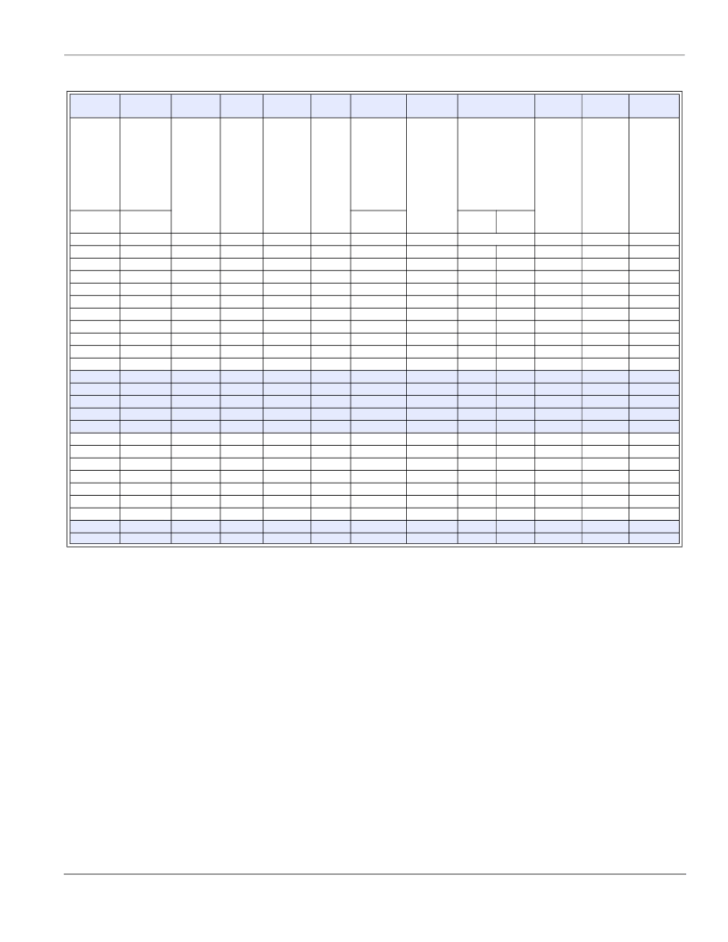
Electrical Specification Notes
(1)
For either polarity of MT2 with reference to MT1 terminal
(2)
For either polarity of gate voltage (V
GT
) with reference to MT1
terminal
See Gate Characteristics and Definition of Quadrants.
See Figure E2.1 through Figure E2.7 for current rating at specific
operating temperature.
See Figure E2.8 through Figure E2.10 for i
T
versus v
T
.
See Figure E2.12 for V
GT
versus T
C
.
See Figure E2.11 for I
GT
versus T
C
.
See Figure E2.14 for I
H
versus T
C
.
See Figure E2.13 for surge rating with specific durations.
(10) See Figure E2.15 for t
gt
versus I
GT
.
(11) See package outlines for lead form configurations. When ordering
special lead forming, add type number as suffix to part number.
(12) Initial on-state current = 200 mA dc for 0.8 A to10 A devices,
400 mA dc for 15 A to 35 A devices
(13) See Figure E2.1 through Figure E2.6 for maximum allowable case
temperature at maximum rated current.
(14) Pulse width
≤
10
μ
s;
I
GT
≤
I
GTM
(3)
(4)
(5)
(6)
(7)
(8)
(9)
(15) R
L
= 60
for 0.8 A to10 A triacs; R
L
= 30
for 15 A to 35 A triacs
(16) T
C
= T
J
for test conditions in off state
(17) I
GT
= 300 mA for 25 A and 35 A devices
(18) Quadrants I, II, III only
(19) Minimum non-trigger V
GT
at 125 °C is 0.2 V for all except 50 mA
MAX QIV devices which are 0.2 V at 110 °C.
Gate Characteristics
Teccor triacs may be turned on between gate and MT1 terminals
in the following ways:
In-phase signals (with standard AC line) using Quadrants I
and III
Application of unipolar pulses (gate always positive or nega-
tive), using Quadrants II and III with negative gate pulses and
Quadrants I and IV with positive gate pulses
However, due to higher gate requirements for Quadrant IV, it
is recommended that only negative pulses be applied. If pos-
itive pulses are required, see “Sensitive Triacs” section of
this catalog or contact the factory. Also, see
Figure AN1002.8, “Amplified Gate” Thyristor Circuit.
V
TM
(1) (5)
V
GT
I
H
I
GTM
(14)
P
GM
(14)
P
G(AV)
I
TSM
(9) (13)
dv/dt(c)
(1) (4) (13)
dv/dt
(1)
t
gt
I
2
t
di/dt
Volts
(2) (6) (15)
(18) (19)
Volts
(1) (8) (12)
mAmps
Amps
Watts
Watts
Amps
Volts/μSec
Volts/
μ
Sec
T
=
100 °C
MIN
150
150
100
75
50
350
350
300
250
150
400
400
350
300
200
400
400
350
300
200
550
450
550
450
(10) (17)
μSec
Amps
2
Sec
Amps/μSec
T
C
= 25 °C
MAX
1.6
1.6
1.6
1.6
1.6
1.6
1.6
1.6
1.6
1.6
1.6
1.6
1.6
1.6
1.6
1.8
1.8
1.8
1.8
1.8
1.4
1.4
1.5
1.5
T
C
= 25 °C
MAX
2.5
2.5
2.5
2.5
2.5
2.5
2.5
2.5
2.5
2.5
2.5
2.5
2.5
2.5
2.5
2.5
2.5
2.5
2.5
2.5
2.75
2.75
2.75
2.75
60/50 Hz
T
=
125 °C
MAX
35
35
35
35
35
50
50
50
50
50
70
70
70
70
70
100
100
100
100
100
50
50
50
50
TYP
2
2
2
2
2
4
4
4
4
4
4
4
4
4
4
5
5
5
5
5
5
5
5
5
TYP
3
3
3
3
3
3
3
3
3
3
4
4
4
4
4
4
4
4
4
4
3
3
3
3
1.8
1.8
1.8
1.8
1.8
1.8
1.8
1.8
1.8
1.8
2
2
2
2
2
2
2
2
2
2
2
2
2
2
20
20
20
20
20
20
20
20
20
20
20
20
20
20
20
20
20
20
20
20
20
20
20
20
0.5
0.5
0.5
0.5
0.5
0.5
0.5
0.5
0.5
0.5
0.5
0.5
0.5
0.5
0.5
0.5
0.5
0.5
0.5
0.5
0.5
0.5
0.5
0.5
120/100
120/100
120/100
120/100
120/100
120/100
120/100
120/100
120/100
120/100
200/167
200/167
200/167
200/167
200/167
200/167
200/167
200/167
200/167
200/167
250/220
250/220
350/300
350/300
60
60
60
60
60
60
60
60
60
60
166
166
166
166
166
166
166
166
166
166
260
260
508
508
70
70
70
70
70
70
70
70
70
70
100
100
100
100
100
100
100
100
100
100
100
100
100
100
225
225
200
175
275
275
225
200
275
275
225
200
475
400
475
400
相關(guān)PDF資料 |
PDF描述 |
|---|---|
| BT136-500D | 3.3-V Phase-Lock Look Clock Driver with Power Down 24-TSSOP 0 to 85 |
| BT136-500E | 3.3-V Phase-Lock Loop Clock Driver 24-TSSOP 0 to 85 |
| BT136-500F | Thyristor Product Catalog |
| BT136-500G | Thyristor Product Catalog |
| BT136-600D | Thyristor Product Catalog |
相關(guān)代理商/技術(shù)參數(shù) |
參數(shù)描述 |
|---|---|
| BT136-500/B | 制造商:未知廠家 制造商全稱:未知廠家 功能描述:TRIAC 4A/500V |
| BT136-500D | 制造商:TECCOR 制造商全稱:TECCOR 功能描述:Thyristor Product Catalog |
| BT136-500E | 制造商:PHILIPS 制造商全稱:NXP Semiconductors 功能描述:Triacs sensitive gate |
| BT136-500F | 制造商:TECCOR 制造商全稱:TECCOR 功能描述:Thyristor Product Catalog |
| BT136-500G | 制造商:TECCOR 制造商全稱:TECCOR 功能描述:Thyristor Product Catalog |
發(fā)布緊急采購,3分鐘左右您將得到回復(fù)。