- 您現(xiàn)在的位置:買(mǎi)賣IC網(wǎng) > PDF目錄366544 > Am53CF96 (Advanced Micro Devices, Inc.) Enhanced SCSI-2 Controller (ESC) PDF資料下載
參數(shù)資料
| 型號(hào): | Am53CF96 |
| 廠商: | Advanced Micro Devices, Inc. |
| 英文描述: | Enhanced SCSI-2 Controller (ESC) |
| 中文描述: | 增強(qiáng)型SCSI - 2控制器(調(diào)速器) |
| 文件頁(yè)數(shù): | 20/76頁(yè) |
| 文件大小: | 735K |
| 代理商: | AM53CF96 |
第1頁(yè)第2頁(yè)第3頁(yè)第4頁(yè)第5頁(yè)第6頁(yè)第7頁(yè)第8頁(yè)第9頁(yè)第10頁(yè)第11頁(yè)第12頁(yè)第13頁(yè)第14頁(yè)第15頁(yè)第16頁(yè)第17頁(yè)第18頁(yè)第19頁(yè)當(dāng)前第20頁(yè)第21頁(yè)第22頁(yè)第23頁(yè)第24頁(yè)第25頁(yè)第26頁(yè)第27頁(yè)第28頁(yè)第29頁(yè)第30頁(yè)第31頁(yè)第32頁(yè)第33頁(yè)第34頁(yè)第35頁(yè)第36頁(yè)第37頁(yè)第38頁(yè)第39頁(yè)第40頁(yè)第41頁(yè)第42頁(yè)第43頁(yè)第44頁(yè)第45頁(yè)第46頁(yè)第47頁(yè)第48頁(yè)第49頁(yè)第50頁(yè)第51頁(yè)第52頁(yè)第53頁(yè)第54頁(yè)第55頁(yè)第56頁(yè)第57頁(yè)第58頁(yè)第59頁(yè)第60頁(yè)第61頁(yè)第62頁(yè)第63頁(yè)第64頁(yè)第65頁(yè)第66頁(yè)第67頁(yè)第68頁(yè)第69頁(yè)第70頁(yè)第71頁(yè)第72頁(yè)第73頁(yè)第74頁(yè)第75頁(yè)第76頁(yè)
P R E L I M I N A R Y
AMD
20
Am53CF94/Am53CF96
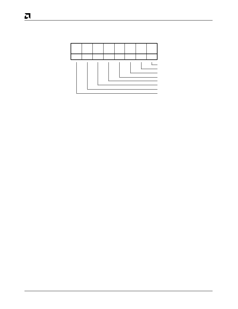
Status Register (04H) Read
Status Register
STATREG
Address: 04
H
Type: Read
7
6
5
4
3
2
1
0
INT
IOE
PE
CTZ
GCV
MSG
C/D
I/O
0
0
0
0
0
x
x
x
Illegal Operation Error
Interrupt
Parity Error
Count to Zero
Group Code Valid
Message
Command/Data
Input/Output
17348B-20
This read only register contains flags to indicate the
status and phase of the SCSI transactions. It indicates
whether an interrupt or error condition exists. It should
be read every time the host is interrupted to determine
which device is asserting an interrupt. If the ENF bit is
set (CNTLREG2, bit 6), the SCSI bus phase of the last
complete command (preceding the interrupt) will be
latched until the Interrupt Status Register (INSTREG) is
read. If the ENF bit is disabled, this register will reflect
the current bus phase. If command stacking is used, two
interrupts might occur. Reading this register will clear
the status information for the first interrupt and update
the Status Register for the second interrupt.
STATREG – Bit 7 – INT – Interrupt
The INT bit is set when the device asserts the interrupt
output. This bit will be cleared by a hardware or software
reset. Reading the Interrupt Status Register (INSTREG)
will deassert the interrupt output and also clear this bit.
STATREG – Bit 6 – IOE – Illegal Operation Error
The IOE bit is set when an illegal operation is attempted.
This condition will not cause an interrupt, it will be de-
tected by reading the Status Register (STATREG) while
servicing another interrupt. The following conditions will
cause the IOE bit to be set:
DMA and SCSI transfer directions are opposite.
I
FIFO overflows or data is overwritten.
I
In Initiator mode an unexpected phase change
detected during synchronous data transfer.
I
Command Register overwritten.
This bit will be cleared by reading the Interrupt Status
Register (INSTREG) or by a hard or soft reset.
I
STATREG – Bit 5 – PE – Parity Error
The PE bit is set if any of the parity checking options are
enabled and the device detects a parity error on bytes
sent or received on the SCSI Bus. Parity options are
controlled by bits 5:4 in Control Register One
(CNTLREG1), and by bits 2:0 in Control Register Two
(CNTLREG2). The combination of enabled options will
determine if parity is generated from the data bytes
internally by the chip, or if it is passed between buffer
and SCSI Bus without being altered. Detection of a
parity error condition will not cause an interrupt but will
be reported with other interrupt causing conditions.
This bit will be cleared by reading the Interrupt Status
Register (INSTREG) or by a hard or soft reset.
STATREG – Bit 4 – CTZ – Count To Zero
The CTZ bit is set when the Current Transfer Count
Register (CTCREG) has counted down to zero. This bit
will be reset when the CTCREG is written with a non-
zero value.
Reading the Interrupt Status Register (INSTREG) will
not affect this bit. This bit will however be cleared by a
hard or soft reset.
Note:
A non-DMA NOP will not reset the CTZ bit since it does
not load the CTCREG. However, a DMA NOP will reset
this bit since it loads the CTCREG.
STATREG – Bit 3 – GCV – Group Code Valid
The GCV bit is set if the group code field in the Com-
mand Descriptor Block (CDB) is one that is defined by
the ANSI Committee in their document X3.131 – 1986. If
the SCSI-2 Feature Enable (S2FE) bit in the Control
Register 2 (CNTLREG2) is set, Group 2 commands will
be treated as ten byte commands and the GCV bit will be
set. If S2FE is reset then Group 2 commands will be
treated as reserved commands. Group 3 and 4 com-
mands will always be considered reserved commands.
The device will treat all reserved commands as six byte
commands. Group 6 commands will always be treated
as vendor unique six byte commands and Group 7 com-
mands will always be treated as vendor unique ten byte
commands.
The GCV bit is cleared by reading the Interrupt Status
Register (INSTREG) or by a hard or soft reset.
相關(guān)PDF資料 |
PDF描述 |
|---|---|
| Am53CF96JC | Enhanced SCSI-2 Controller (ESC) |
| Am53CF96JCW | Enhanced SCSI-2 Controller (ESC) |
| AM53CF96KC | Enhanced SCSI-2 Controller (ESC) |
| Am53CF96KCW | Enhanced SCSI-2 Controller (ESC) |
| AM545LS374A | 8-Bit Registers with Three-State Outputs |
相關(guān)代理商/技術(shù)參數(shù) |
參數(shù)描述 |
|---|---|
| AM53CF96JC | 制造商:AMD 制造商全稱:Advanced Micro Devices 功能描述:Enhanced SCSI-2 Controller (ESC) |
| AM53CF96JCW | 制造商:AMD 制造商全稱:Advanced Micro Devices 功能描述:Enhanced SCSI-2 Controller (ESC) |
| AM53CF96KC | 制造商:Rochester Electronics LLC 功能描述:- Bulk 制造商:Advanced Micro Devices 功能描述: 制造商:AMD 功能描述: |
| AM53CF96KCW | 制造商:AMD 制造商全稱:Advanced Micro Devices 功能描述:Enhanced SCSI-2 Controller (ESC) |
| AM5400N | 制造商:ANALOGPOWER 制造商全稱:ANALOGPOWER 功能描述:N-Channel 100-V (D-S) MOSFET |
發(fā)布緊急采購(gòu),3分鐘左右您將得到回復(fù)。