- 您現(xiàn)在的位置:買賣IC網(wǎng) > PDF目錄375301 > AM29PL320DB60RWPI (SPANSION LLC) 32 Megabit (2 M x 16-Bit/1 M x 32-Bit) CMOS 3.0 Volt-only High Performance Page Mode Flash Memory PDF資料下載
參數(shù)資料
| 型號: | AM29PL320DB60RWPI |
| 廠商: | SPANSION LLC |
| 元件分類: | DRAM |
| 英文描述: | 32 Megabit (2 M x 16-Bit/1 M x 32-Bit) CMOS 3.0 Volt-only High Performance Page Mode Flash Memory |
| 中文描述: | 1M X 32 FLASH 3V PROM, 60 ns, PBGA84 |
| 封裝: | 11 X 12 MM, 0.80 MM PITCH, FBGA-84 |
| 文件頁數(shù): | 16/50頁 |
| 文件大小: | 947K |
| 代理商: | AM29PL320DB60RWPI |
第1頁第2頁第3頁第4頁第5頁第6頁第7頁第8頁第9頁第10頁第11頁第12頁第13頁第14頁第15頁當(dāng)前第16頁第17頁第18頁第19頁第20頁第21頁第22頁第23頁第24頁第25頁第26頁第27頁第28頁第29頁第30頁第31頁第32頁第33頁第34頁第35頁第36頁第37頁第38頁第39頁第40頁第41頁第42頁第43頁第44頁第45頁第46頁第47頁第48頁第49頁第50頁
14
Am29PL320D
October 2, 2003
Autoselect Mode
The autoselect mode provides manufacturer and de-
vice identification, and sector protection verification,
through identifier codes output on DQ7–DQ0. This
mode is primarily intended for programming equipment
to automatically match a device to be programmed
with its corresponding programming algorithm. How-
ever, the autoselect codes can also be accessed in-
system through the command register.
When using programming equipment, the autoselect
mode requires V
ID
(11.5 V to 12.5 V) on address input
A9. Address inputs must be as shown in Table 8. In ad-
dition, when verifying sector protection, the sector
address must appear on the appropriate highest order
address bits (Table 4). Table 8 shows the remaining
address bits that are don’t care. When all necessary
bits have been set as required, the programming
equipment may then read the corresponding identifier
code on DQ7-DQ0.
To access the autoselect codes in-system, the host
system can issue the autoselect command via the
command register, as shown in Table 13. This method
does not require V
ID
. See “Command Definitions” for
details on using the autoselect mode.
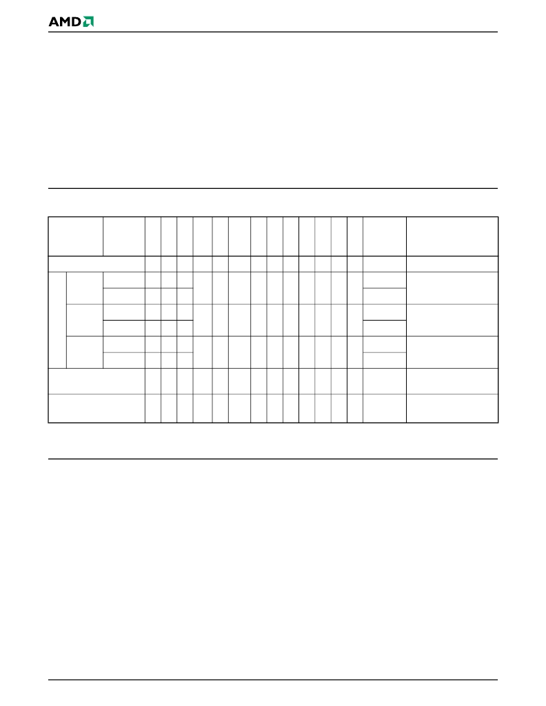
Table 8.
Am29PL320D Autoselect Codes (High Voltage Method)
L = Logic Low = V
IL
, H = Logic High = V
IH
, SA = Sector Address, X = Don’t care.
Note:
The autoselect codes may also be accessed in-system via command sequences. See Table 13.
Sector Protection/Unprotection
The hardware sector protection feature disables both
program and erase operations in any sector.
The hardware sector unprotection feature re-enables
both program and erase operations in previously
protected sectors.
The device is shipped with all sectors unprotected.
AMD offers the option of programming and protecting
sectors at its factory prior to shipping the device
through AMD’s ExpressFlash Service. Contact an
AMD representative for details.
It is possible to determine whether a sector is protected
or unprotected. See “Autoselect Mode” for details.
Sector protection and unprotection must be imple-
mented via programming equipment. The procedure
requires high voltage (V
ID
) to be placed on address
input A9 and control input OE#. This method is com-
patible with programmer routines written for earlier
AMD 3.0 volt devices. Publication number 24136 con-
tains further details; contact an AMD representative to
request a copy. For sector unprotect, all unprotected
sectors must first be protected prior to the first sector
unprotect write cycle. Note that after the sector unpro-
tect operation, all previously protected sectors must be
re-protected using the sector protect algorithm.
The device features a temporary unprotect command
sequence to allow changing array data in-system. See
“Temporary Sector Unprotect Enable/Disable
Command Sequence” for more information.
Description
Mode
C
O
W
A
A
A
A
A
A
A
A
A
A
DQ31–
DQ8
DQ7–DQ0
Manufacturer ID
:
AMD
L
L
H
X
X
V
ID
X
L
X
X
X
L
L
X
01h
D
Read
Cycle 1
Word
L
L
H
X
X
V
ID
X
L
X
L
L
L
H
22h
7Eh
Dbl. Word
L
L
H
222222h
Read
Cycle 2
Word
L
L
H
X
X
V
ID
X
L
X
H
H
H
L
22h
03h
Dbl. Word
L
L
H
222222h
Read
Cycle 3
Word
L
L
H
X
X
V
ID
X
L
X
H
H
H
H
22h
00h (bottom boot)
01h (top boot)
Dbl. Word
L
L
H
222222h
SecSi
Sector Indicator
Bit
L
L
H
X
X
V
ID
X
L
X
L
L
H
H
X
80h (factory locked)
00h (not factory locked)
Sector Protection
Verification
L
L
H
SA
X
V
ID
X
L
X
L
L
H
L
X
01h (protected)
00h (unprotected)
相關(guān)PDF資料 |
PDF描述 |
|---|---|
| AM29PL320DB70RWPI | 32 Megabit (2 M x 16-Bit/1 M x 32-Bit) CMOS 3.0 Volt-only High Performance Page Mode Flash Memory |
| AM29PL320DT60RWPI | 32 Megabit (2 M x 16-Bit/1 M x 32-Bit) CMOS 3.0 Volt-only High Performance Page Mode Flash Memory |
| AM29PL320DT70RWPI | 32 Megabit (2 M x 16-Bit/1 M x 32-Bit) CMOS 3.0 Volt-only High Performance Page Mode Flash Memory |
| AM2D-0505DH30-N | 2 watt dc-dc converters |
| AM2D-0505D-N | 2 watt dc-dc converters |
相關(guān)代理商/技術(shù)參數(shù) |
參數(shù)描述 |
|---|---|
| AM29SL160CT-100EIN | 制造商:Advanced Micro Devices 功能描述: |
| AM29SL800DB120WCI | 制造商:Spansion 功能描述:FLASH PARALLEL 1.8V 8MBIT 1MX8/512KX16 120NS 48FBGA - Trays |
| AM29SL800DB90WAD | 制造商:Spansion 功能描述: |
| AM29X305ADC | 制造商:Advanced Micro Devices 功能描述:Microprocessor, 8 Bit, 50 Pin, Ceramic, DIP |
| AM2A016 | 制造商:MAG-LITE 功能描述:Bulk |
發(fā)布緊急采購,3分鐘左右您將得到回復(fù)。