- 您現(xiàn)在的位置:買賣IC網(wǎng) > PDF目錄375282 > ALA2PF24 2 Form A slim power relay PDF資料下載
參數(shù)資料
| 型號: | ALA2PF24 |
| 英文描述: | 2 Form A slim power relay |
| 中文描述: | 2 A型微功率繼電器 |
| 文件頁數(shù): | 1/3頁 |
| 文件大小: | 60K |
| 代理商: | ALA2PF24 |
LA
275
LA RELAYS
2 Form A slim power relay
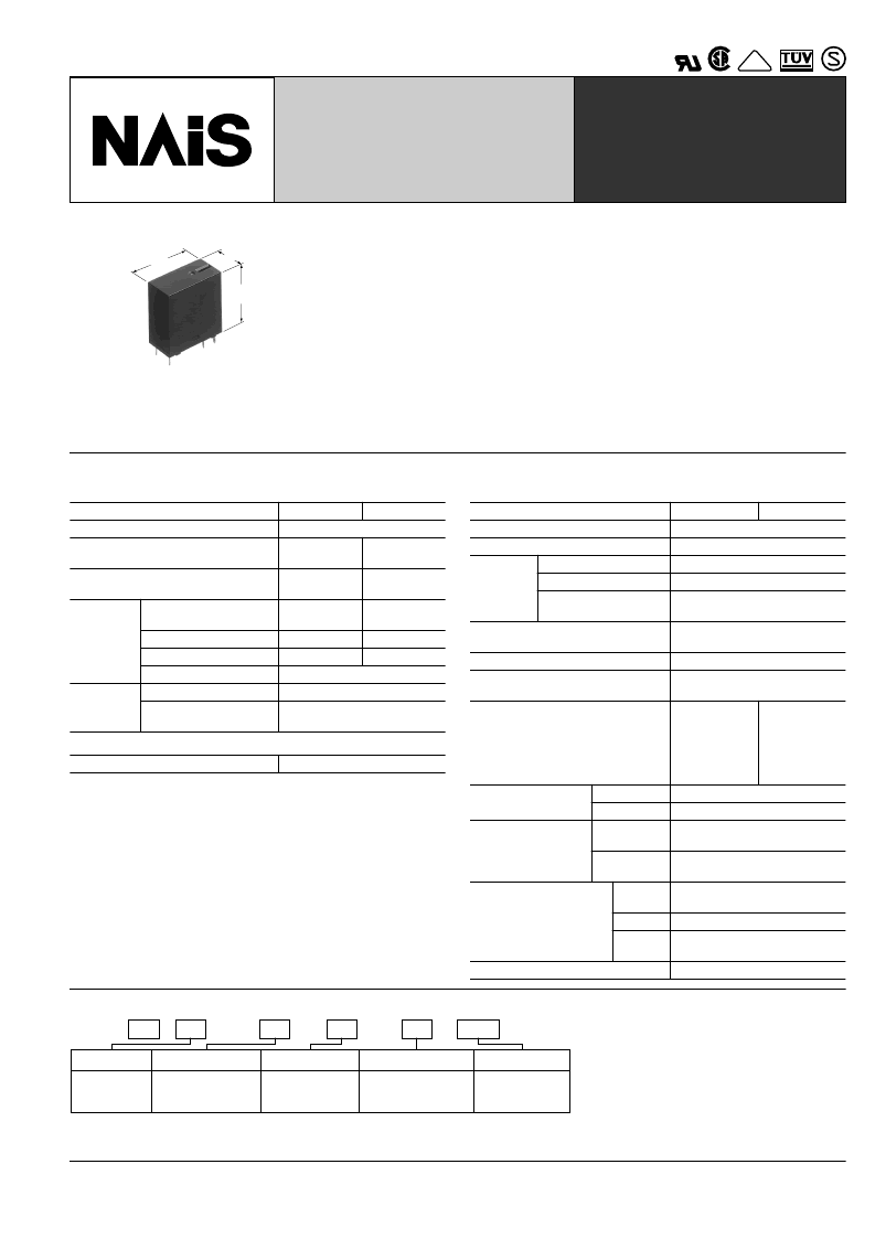
mm
inch
25.0
.984
24.0
.945
12.0
.472
FEATURES
1. 2 Form A slim type
24(L)
×
12(W)
.945(L)
×
.472(W)
2. 3A type and 5A TV type
3A type: Contact reliability and break per-
formance best suited for protecting and
switching speakers.
5A TV type: Tough against inrush current
and optimal for turning on and off the pow-
er supply. Rated TV-4 (UL/CSA).
3. High insulation resistance
Creepage distance and clearances be-
×
25(H) mm
×
.984(H) inch
tween contact and coil: Min. 6 mm
.236
inch
(In compliance with IEC65)
Surge withstand voltage between con-
tact and coil: 10,000 V or more.
4. High noise immunity realized by the
card separation structure between
contact and coil
5. Conforms to the various safety stan-
dards
UL/CSA, VDE, TüV, SEMKO, SEV ap-
proved
SPECIFICATIONS
Contact
Type
Arrangement
Initial contact resistance, max.
(By voltage drop 6 V DC 1 A)
Coil
Nominal operating power
Remarks
* Specifications will vary with foreign standards certification ratings.
*
Measurement at same location as "Initial breakdown voltage" section.
*
Detection current: 10mA
*
Wave is standard shock voltage of
*
Excluding contact bounce time.
*
Half-wave pulse of sine wave: 11 ms; detection time: 10
*
Half-wave pulse of sine wave: 6 ms
*
Detection time: 10
μ
s
*
Refer to 5. Conditions for operation, transport and storage mentioned in
AMBIENT ENVIRONMENT (Page 61).
1
2
3
±
1.2
×
50ms according to JEC-212-1981
4
5
μ
s
6
7
8
Characteristics
Type
Max. operating speed
Initial insulation resistance*
Between contact sets
Between open contacts
Between contact and
coil
Surge voltage between contact and
coil*
Operate time*
(at nominal voltage)
Release time (with diode)*
(at nominal voltage)
3A rated
5A TV rated
2 Form A
Max. 50 m
Max. 100 m
Contact material
Gold-clad
silver alloy
Silver alloy
Rating
(resistive
load)
Nominal switching
capacity
Max. switching power
Max. switching voltage
Max. switching current
Mechanical (at 180 cpm)
Electrical (at 20 cpm)
(at rated load)
3 A 125 V AC
5 A 277 V AC
625 VA
125 V AC
1,385 V A
277 V AC
5 A (AC)
10
5
×
10
Expected
life (min.
operations)
6
4
(ON: OFF=1.5s: 1.5s)
530 mW
3A rated
5A TV rated
20 cpm
1
Min. 1,000 M
1,000 Vrms for 1 min.
1,000 Vrms for 1 min.
(at 500 V DC)
Initial *
breakdown
voltage
2
4,000 Vrms for 1 min.
3
Min. 10,000 V
4
Max. 15ms (at 20
°
C
68
°
F
)
4
Max. 15ms (at 20
°
C
68
°
F
)
Temperature rise (at 70
°
C)
Max. 45
with nominal
coil voltage
and at 3 A
contact car-
rying current
Min. 200 m/s
Min. 1,000 m/s
°
C
Max. 45
with nominal
coil voltage
and at 5 A
contact car-
rying current
{approx. 20 G}
{approx. 100 G}
10 to 55Hz
at double amplitude of 1.5mm
10 to 55Hz
at double amplitude of 1.5mm
–40
°
C to +70
–40
°
F to +158
5 to 85% R.H.
°
C
Shock resistance
Functional*
Destructive*
5
2
6
2
Vibration resistance
Functional*
7
Destructive
Conditions for operation,
transport and storage*
(Not freezing and con-
densing at low tempera-
ture)
8
Ambient
temp.
Humidity
Air
pressure
°
C
°
F
86 to 106 kPa
Unit weight
Approx. 13 g
.46 oz
ORDERING INFORMATION
Ex.
LA
A
Contact arrangement
Contact capacity
Protective construction Coil voltage(V DC)
2: 2 Form A
Nil: 3A
P: 5A TV-4
F: Flux-resistant type
12, 24
2
Product name
LA
F
12
P
UL/CSA, VDE, TüV, SEMKO, TV-4 approved type is standard.
Notes: 1. Standard packing Carton: 100 pcs. Case: 500 pcs.
2. 4.5V, 5V, 9V and 18V DC types are also available. Please consult us for details.
VDE
相關(guān)PDF資料 |
PDF描述 |
|---|---|
| Alpha 21164 | Alpha Microprocessor(64位微處理器) |
| AlphaPC 164BX | Motherboard(主板) |
| AlphaPC 164UX | Motherboard(主板) |
| ALR006 | 14 pin DIP, 5.0 Volt, HCMOS/TTL, Clock Oscillator |
| ALR015 | Circular Connector; No. of Contacts:37; Series:MS27497; Body Material:Aluminum; Connecting Termination:Crimp; Connector Shell Size:14; Circular Contact Gender:Socket; Circular Shell Style:Wall Mount Receptacle RoHS Compliant: No |
相關(guān)代理商/技術(shù)參數(shù) |
參數(shù)描述 |
|---|---|
| ALA2PF24T | 制造商:Panasonic Electric Works 功能描述: |
| ALA2PF4H | 功能描述:通用繼電器 2 Form A 5A 277VAC 4.5VDC RoHS:否 制造商:Omron Electronics 觸點形式:1 Form A (SPST-NO) 觸點電流額定值:150 A 線圈電壓:24 VDC 線圈電阻:144 Ohms 線圈電流:167 mA 切換電壓:400 V 安裝風(fēng)格:Chassis 觸點材料: |
| ALA2PF5T | 制造商:Panasonic Electric Works 功能描述: |
| ALA2PFB06 | 功能描述:通用繼電器 2 Form A 5A TV-4 6VDC RoHS:否 制造商:Omron Electronics 觸點形式:1 Form A (SPST-NO) 觸點電流額定值:150 A 線圈電壓:24 VDC 線圈電阻:144 Ohms 線圈電流:167 mA 切換電壓:400 V 安裝風(fēng)格:Chassis 觸點材料: |
| ALA30020501 | 制造商:LG Corporation 功能描述:BMS LCD Assembly |
發(fā)布緊急采購,3分鐘左右您將得到回復(fù)。