- 您現(xiàn)在的位置:買賣IC網(wǎng) > PDF目錄373981 > ADE7768AR-REF (Analog Devices, Inc.) Energy Metering IC with Integrated Oscillator and Positive Power Accumulation PDF資料下載
參數(shù)資料
| 型號: | ADE7768AR-REF |
| 廠商: | Analog Devices, Inc. |
| 英文描述: | Energy Metering IC with Integrated Oscillator and Positive Power Accumulation |
| 中文描述: | 電能計量IC整合的振蕩器和積累的積極力量 |
| 文件頁數(shù): | 10/20頁 |
| 文件大?。?/td> | 299K |
| 代理商: | ADE7768AR-REF |
ADE7768
FUNCTIONAL DESCRIPTION
THEORY OF OPERATION
The two ADCs in the ADE7768 digitize the voltage signals from
the current and voltage sensors. These ADCs are 16-bit Σ-Δs
with an oversampling rate of 450 kHz. This analog input
structure greatly simplifies sensor interfacing by providing a
wide dynamic range for direct connection to the sensor and
by simplifying the antialiasing filter design. A high-pass filter
in the current channel removes any dc component from the
current signal. This eliminates any inaccuracies in the real
power calculation due to offsets in the voltage or current
signals.
Rev. A | Page 10 of 20
The real power calculation is derived from the instantaneous
power signal. The instantaneous power signal is generated by
a direct multiplication of the current and voltage signals. To
extract the real power component (the dc component), the
instantaneous power signal is low-pass filtered. Figure 15
illustrates the instantaneous real power signal and shows how
the real power information can be extracted by low-pass
filtering the instantaneous power signal. In the ADE7768,
this signal is compared to 0 and only positive real power is
accumulated for F1, F2, and CF pulse outputs. This scheme
correctly calculates real power for sinusoidal current and
voltage waveforms at all power factors. All signal processing
is carried out in the digital domain for superior stability over
temperature and time.
TIME
TIME
ADC
ADC
CH1
CH2
MULTIPLIER
F1
F2
DIGITAL-TO-
CF
DIGITAL-TO-
INSTANTANEOUS REAL
POWER SIGNAL
INSTANTANEOUS
POWER SIGNAL – p(t)
LPF
HPF
0
≥
0
Figure 15. Signal Processing Block Diagram
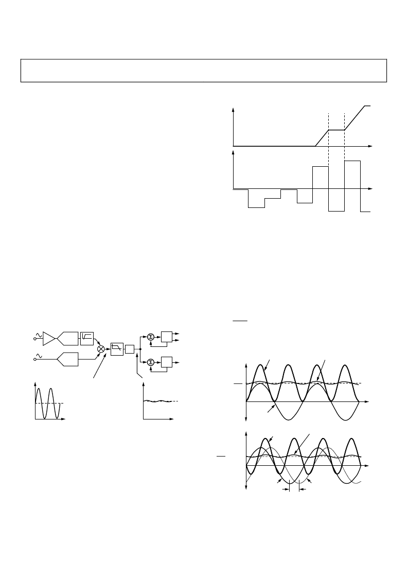
The low frequency outputs (F1 and F2) are generated by
accumulating positive-only real power information. This low
frequency inherently means a long accumulation time between
output pulses. Consequently, the resulting output frequency is
proportional to the average positive-only real power. This
average positive-only real power information is then accumu-
lated (by a counter) to generate real energy information (see
Figure 16). Conversely, due to its high output frequency and
shorter integration time, the CF output frequency is propor-
tional to the instantaneous positive-only real power. This is
useful for system calibration, which can be done faster under
steady load conditions.
ACTIVE ENERGY
INSTANTANEOUS
POWER
M
M
0Wh
0W
0
Figure 16. Positive-Only Energy Accumulation
Power Factor Considerations
The method used to extract the real power information from
the instantaneous power signal (that is, by low-pass filtering) is
still valid even when the voltage and current signals are not in
phase. Figure 17 displays the unity power factor condition and a
displacement power factor (DPF) = 0.5 (a current signal lagging
the voltage by 60°). Assuming that the voltage and current
waveforms are sinusoidal, the real power component of the
instantaneous power signal (that is, the dc term) is given by
(
°
×
×
2
60
cos
I
V
)
(1)
This is the correct real power calculation.
V
×
I
2
0V
POWER
VOLTAGE
POWER
TIME
TIME
VOLTAGE
CURRENT
V
×
I
2
COS (60
°
)
0V
IPOWER SIGNAL
INSPOWER SIGNAL
IPOWER SIGNAL
INSPOWER SIGNAL
60
°
0
Figure 17. DC Component of Instantaneous Power Signal Conveys
Real Power Information, PF < 1
相關(guān)PDF資料 |
PDF描述 |
|---|---|
| ADE7768AR-RL | Energy Metering IC with Integrated Oscillator and Positive Power Accumulation |
| ADE7768ARZ | Energy Metering IC with Integrated Oscillator and Positive Power Accumulation |
| ADE7768ARZ-RL | Energy Metering IC with Integrated Oscillator and Positive Power Accumulation |
| ADEL2020AN | Improved Second Source to the EL2020 |
| ADEL2020AR-20 | Circular Connector Cable Assembly; Connector Type A:Circular Plug; Connector Type B:Stripped End Leads; Cable Length:10ft RoHS Compliant: Yes |
相關(guān)代理商/技術(shù)參數(shù) |
參數(shù)描述 |
|---|---|
| ADE7768AR-RL | 制造商:Analog Devices 功能描述:ENERGY MEASUREMENT 16SOIC - Tape and Reel |
| ADE7768ARZ | 功能描述:IC ENERGY METERING 1PHASE 16SOIC RoHS:是 類別:集成電路 (IC) >> PMIC - 能量測量 系列:- 產(chǎn)品培訓(xùn)模塊:Lead (SnPb) Finish for COTS Obsolescence Mitigation Program 標(biāo)準(zhǔn)包裝:2,500 系列:* |
| ADE7768ARZ-RL | 功能描述:IC ENERGY METERING 1PHASE 16SOIC RoHS:是 類別:集成電路 (IC) >> PMIC - 能量測量 系列:- 產(chǎn)品培訓(xùn)模塊:Lead (SnPb) Finish for COTS Obsolescence Mitigation Program 標(biāo)準(zhǔn)包裝:2,500 系列:* |
| ADE7769 | 制造商:AD 制造商全稱:Analog Devices 功能描述:Energy Metering IC with Integrated Oscillator and No-Load Indication |
| ADE7769AR | 制造商:Analog Devices 功能描述:Energy Measurement 16-Pin SOIC N |
發(fā)布緊急采購,3分鐘左右您將得到回復(fù)。