- 您現(xiàn)在的位置:買(mǎi)賣(mài)IC網(wǎng) > PDF目錄373980 > ADE7758ARWZRL (ANALOG DEVICES INC) Poly Phase Multifunction Energy Metering IC with Per Phase Information PDF資料下載
參數(shù)資料
| 型號(hào): | ADE7758ARWZRL |
| 廠商: | ANALOG DEVICES INC |
| 元件分類: | 模擬信號(hào)調(diào)理 |
| 英文描述: | Poly Phase Multifunction Energy Metering IC with Per Phase Information |
| 中文描述: | SPECIALTY ANALOG CIRCUIT, PDSO24 |
| 封裝: | LEAD FREE, MS-013-AD, SOIC-24 |
| 文件頁(yè)數(shù): | 66/68頁(yè) |
| 文件大小: | 1584K |
| 代理商: | ADE7758ARWZRL |
第1頁(yè)第2頁(yè)第3頁(yè)第4頁(yè)第5頁(yè)第6頁(yè)第7頁(yè)第8頁(yè)第9頁(yè)第10頁(yè)第11頁(yè)第12頁(yè)第13頁(yè)第14頁(yè)第15頁(yè)第16頁(yè)第17頁(yè)第18頁(yè)第19頁(yè)第20頁(yè)第21頁(yè)第22頁(yè)第23頁(yè)第24頁(yè)第25頁(yè)第26頁(yè)第27頁(yè)第28頁(yè)第29頁(yè)第30頁(yè)第31頁(yè)第32頁(yè)第33頁(yè)第34頁(yè)第35頁(yè)第36頁(yè)第37頁(yè)第38頁(yè)第39頁(yè)第40頁(yè)第41頁(yè)第42頁(yè)第43頁(yè)第44頁(yè)第45頁(yè)第46頁(yè)第47頁(yè)第48頁(yè)第49頁(yè)第50頁(yè)第51頁(yè)第52頁(yè)第53頁(yè)第54頁(yè)第55頁(yè)第56頁(yè)第57頁(yè)第58頁(yè)第59頁(yè)第60頁(yè)第61頁(yè)第62頁(yè)第63頁(yè)第64頁(yè)第65頁(yè)當(dāng)前第66頁(yè)第67頁(yè)第68頁(yè)
ADE7758
INTERRUPT STATUS REGISTER (0x19)/RESET INTERRUPT STATUS REGISTER (0x1A)
The interrupt status register is used to determine the source of an interrupt event. When an interrupt event occurs in the ADE7758, the
corresponding flag in the interrupt status register is set logic high. The IRQ pin goes active low if the corresponding bit in the interrupt
mask register is set logic high. When the MCU services the interrupt, it must first carry out a read from the interrupt status register to
determine the source of the interrupt. All the interrupts in the interrupt status register stay at their logic high state after an event occurs.
The state of the interrupt bit in the interrupt status register is reset to its default value once the reset interrupt status register is read.
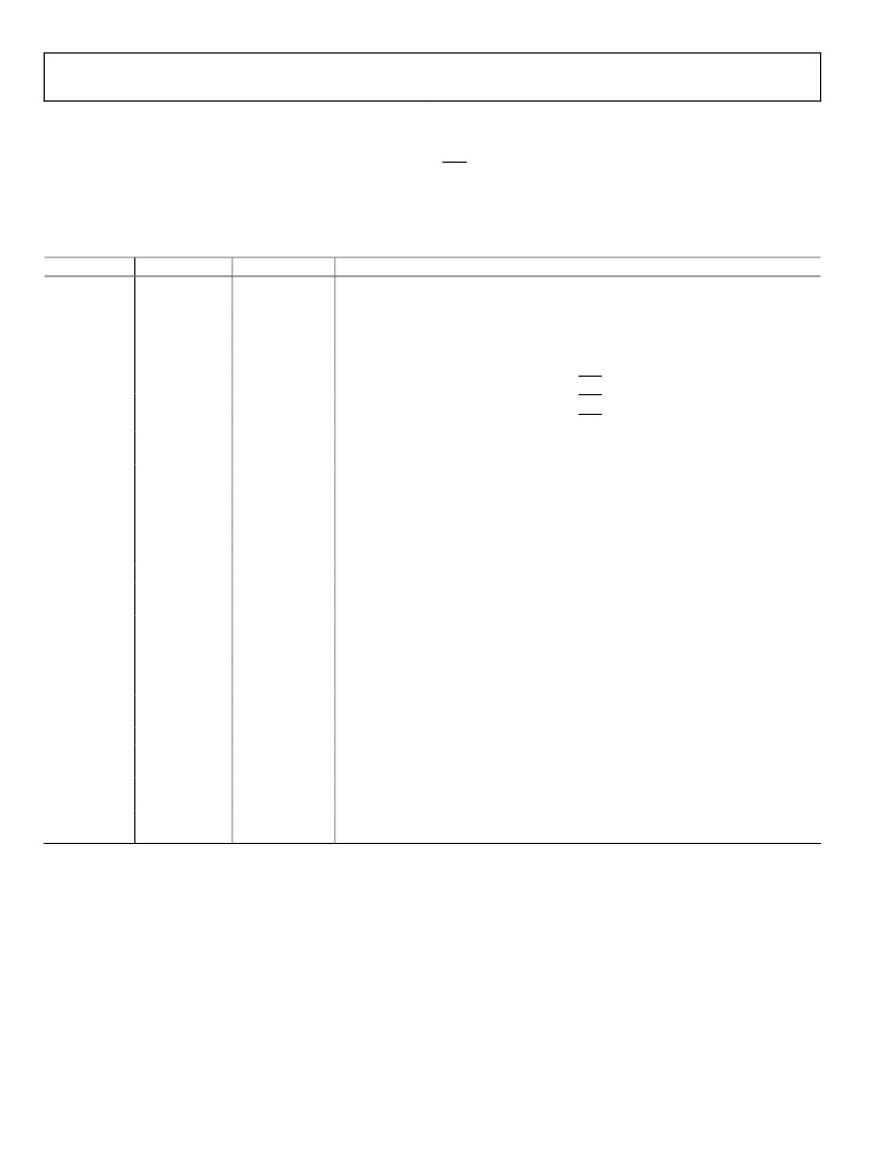
Table 20. Interrupt Status Register
Bit Location
Interrupt Flag
Default Value
Event Description
Indicates that an interrupt was caused by a change in Bit 14 among any one of the
three WATTHR registers, i.e., the WATTHR register is half full.
Indicates that an interrupt was caused by a change in Bit 14 among any one of the
three VARHR registers, i.e., the VARHR register is half full.
Indicates that an interrupt was caused by a 0-to-1 transition in Bit 15 among any one
of the three VAHR registers, i.e., the VAHR register is half full.
3
SAGA
0
Indicates that an interrupt was caused by a SAG on the line voltage of the Phase A.
4
SAGB
0
Indicates that an interrupt was caused by a SAG on the line voltage of the Phase B.
5
SAGC
0
Indicates that an interrupt was caused by a SAG on the line voltage of the Phase C.
Indicates that an interrupt was caused by a missing zero crossing on the line voltage
of the Phase A.
Indicates that an interrupt was caused by a missing zero crossing on the line voltage
of the Phase B.
Indicates that an interrupt was caused by a missing zero crossing on the line voltage
of the Phase C.
9
ZXA
0
Indicates a detection of a rising edge zero crossing in the voltage channel of the Phase A.
10
ZXB
0
Indicates a detection of a rising edge zero crossing in the voltage channel of the Phase B.
11
ZXC
0
Indicates a detection of a rising edge zero crossing in the voltage channel of the Phase C.
In line energy accumulation, it indicates the end of an integration over an integer
number of half-line cycles (LINECYC), see the Calibration section.
Indicates that the 5 V power supply is below 4 V. Enables a software reset of the
ADE7758 and sets the registers back to their default values. This bit in the STATUS or
RSTATUS register is logic high for only one clock cycle after a reset event.
Indicates that an interrupt was caused when the selected voltage input is above the
value in the PKVLVL register.
Indicates that an interrupt was caused when the selected current input is above the
value in the PKILVL register.
16
WFSM
0
Indicates that new data is present in the waveform register.
Indicates that an interrupt was caused by a sign change in the watt calculation among
any one of the phases specified by the TERMSEL bits in the COMPMODE register.
Indicates that an interrupt was caused by a sign change in the VAR calculation among
any one of the phases specified by the TERMSEL bits in the COMPMODE register.
Indicates that an interrupt was caused by a zero crossing from Phase A not followed
by the zero crossing of Phase C but by that of Phase B.
Rev. A | Page 66 of 68
0
AEHF
0
1
REHF
0
2
VAEHF
0
6
ZXTOA
0
7
ZXTOB
0
8
ZXTOC
0
12
LENERGY
0
13
RESET
1
14
PKV
0
15
PKI
0
17
REVPAP
0
18
REVPRP
0
19
SEQERR
0
相關(guān)PDF資料 |
PDF描述 |
|---|---|
| ADE7759ARSRL | Active Energy Metering IC with di/dt Sensor Interface |
| ADE7759ARS | 8-Channel 14-Bit Single-Supply Voltage-Output DAC; Package: LQFP (10x10mm); No of Pins: 52; Temperature Range: Industrial |
| ADE7759 | Active Energy Metering IC with di/dt Sensor Interface |
| ADE7760ARSRL | Energy Metering IC with On-Chip Fault Detection |
| ADE7760 | 8-Channel 14-Bit Single-Supply Voltage-Output DAC; Package: LQFP (10x10mm); No of Pins: 52; Temperature Range: Industrial |
相關(guān)代理商/技術(shù)參數(shù) |
參數(shù)描述 |
|---|---|
| ADE7759 | 制造商:AD 制造商全稱:Analog Devices 功能描述:Active Energy Metering IC with di/dt Sensor Interface |
| ADE7759ARS | 功能描述:IC ENERGY METERING 1PHASE 20SSOP RoHS:否 類別:集成電路 (IC) >> PMIC - 能量測(cè)量 系列:- 產(chǎn)品培訓(xùn)模塊:Lead (SnPb) Finish for COTS Obsolescence Mitigation Program 標(biāo)準(zhǔn)包裝:2,500 系列:* |
| ADE7759ARSRL | 功能描述:IC ENERGY METERING 1PHASE 20SSOP RoHS:否 類別:集成電路 (IC) >> PMIC - 能量測(cè)量 系列:- 產(chǎn)品培訓(xùn)模塊:Lead (SnPb) Finish for COTS Obsolescence Mitigation Program 標(biāo)準(zhǔn)包裝:2,500 系列:* |
| ADE7759ARSZ | 功能描述:IC ENERGY METERING 1PHASE 20SSOP RoHS:是 類別:集成電路 (IC) >> PMIC - 能量測(cè)量 系列:- 產(chǎn)品培訓(xùn)模塊:Lead (SnPb) Finish for COTS Obsolescence Mitigation Program 標(biāo)準(zhǔn)包裝:2,500 系列:* |
| ADE7759ARSZRL | 功能描述:IC ENERGY METERING 1PHASE 20SSOP RoHS:是 類別:集成電路 (IC) >> PMIC - 能量測(cè)量 系列:- 產(chǎn)品培訓(xùn)模塊:Lead (SnPb) Finish for COTS Obsolescence Mitigation Program 標(biāo)準(zhǔn)包裝:2,500 系列:* |
發(fā)布緊急采購(gòu),3分鐘左右您將得到回復(fù)。