- 您現(xiàn)在的位置:買賣IC網(wǎng) > PDF目錄373980 > ADE7169ASTF16 (ANALOG DEVICES INC) Single-Phase Energy Measurement IC with 8052 MCU, RTC and LCD driver PDF資料下載
參數(shù)資料
| 型號: | ADE7169ASTF16 |
| 廠商: | ANALOG DEVICES INC |
| 元件分類: | 模擬信號調(diào)理 |
| 英文描述: | Single-Phase Energy Measurement IC with 8052 MCU, RTC and LCD driver |
| 中文描述: | ANALOG CIRCUIT, PQFP64 |
| 封裝: | MS-026BCD, LQFP-64 |
| 文件頁數(shù): | 119/140頁 |
| 文件大小: | 1359K |
| 代理商: | ADE7169ASTF16 |
第1頁第2頁第3頁第4頁第5頁第6頁第7頁第8頁第9頁第10頁第11頁第12頁第13頁第14頁第15頁第16頁第17頁第18頁第19頁第20頁第21頁第22頁第23頁第24頁第25頁第26頁第27頁第28頁第29頁第30頁第31頁第32頁第33頁第34頁第35頁第36頁第37頁第38頁第39頁第40頁第41頁第42頁第43頁第44頁第45頁第46頁第47頁第48頁第49頁第50頁第51頁第52頁第53頁第54頁第55頁第56頁第57頁第58頁第59頁第60頁第61頁第62頁第63頁第64頁第65頁第66頁第67頁第68頁第69頁第70頁第71頁第72頁第73頁第74頁第75頁第76頁第77頁第78頁第79頁第80頁第81頁第82頁第83頁第84頁第85頁第86頁第87頁第88頁第89頁第90頁第91頁第92頁第93頁第94頁第95頁第96頁第97頁第98頁第99頁第100頁第101頁第102頁第103頁第104頁第105頁第106頁第107頁第108頁第109頁第110頁第111頁第112頁第113頁第114頁第115頁第116頁第117頁第118頁當(dāng)前第119頁第120頁第121頁第122頁第123頁第124頁第125頁第126頁第127頁第128頁第129頁第130頁第131頁第132頁第133頁第134頁第135頁第136頁第137頁第138頁第139頁第140頁
Preliminary Technical Data
ADE7169F16
Rev. PrD | Page 119 of 140
300
300
300
300
300
300
300
300
0
1
2
3
4
5
6
7
2
1
0
0
0
0
0
0
7
7
7
6
5
4
3
2
17H
0FH
07H
06H
05H
04H
03H
02H
ABH
ABH
ABH
ABH
ABH
ABH
ABH
ABH
- 0.31
- 0.31
- 0.31
- 0.31
- 0.31
- 0.31
- 0.31
- 0.31
UART OPERATION MODES
Mode 0 (Shift Register with baud rate fixed at
Fcore /12)
Mode 0 is selected when the SM0 and SM1 bits in the SCON
SFR are clear. In this shift register mode, serial data enters and
exits through RxD. TxD outputs the shift clock. The baud rate is
fixed at F
core
/12. Eight data bits are transmitted or received.
Transmission is initiated by any instruction that writes to SBUF.
The data is shifted out of the RxD line. The 8 bits are
transmitted with the least significant bit (LSB) first.
Reception is initiated when the receive enable bit (REN) is 1
and the receive interrupt bit (RI) is 0. When RI is cleared, the
data is clocked into the RxD line, and the clock pulses are
output from the TxD line as shown in Figure 76.
RxD
(DATA OUT)
TxD
(SHIFT CLOCK)
DATA BIT 0
DATA BIT 1
DATA BIT 6
DATA BIT 7
0
Figure 76. 8-Bit Shift Register Mode
Mode 1 (8-Bit UART, Variable Baud Rate)
Mode 1 is selected by clearing SM0 and setting SM1. Each data
byte (LSB first) is preceded by a start bit (0) and followed by a
stop bit (1). Therefore, each frame consists of 10 bits
transmitted on TxD or received on RxD.
The baud rate is set by a timer overflow rate. Timer 1 or Timer
2 can be used to generate baud rates or both timers can be used
simultaneously where one generates the transmit rate and the
other generates the receive rate. There is also a dedicated timer
for baud rate generation, UART Timer, which has a fractional
divisor to precisely generate any baud rate—see the UART
Timer Generated Baud Rates section.
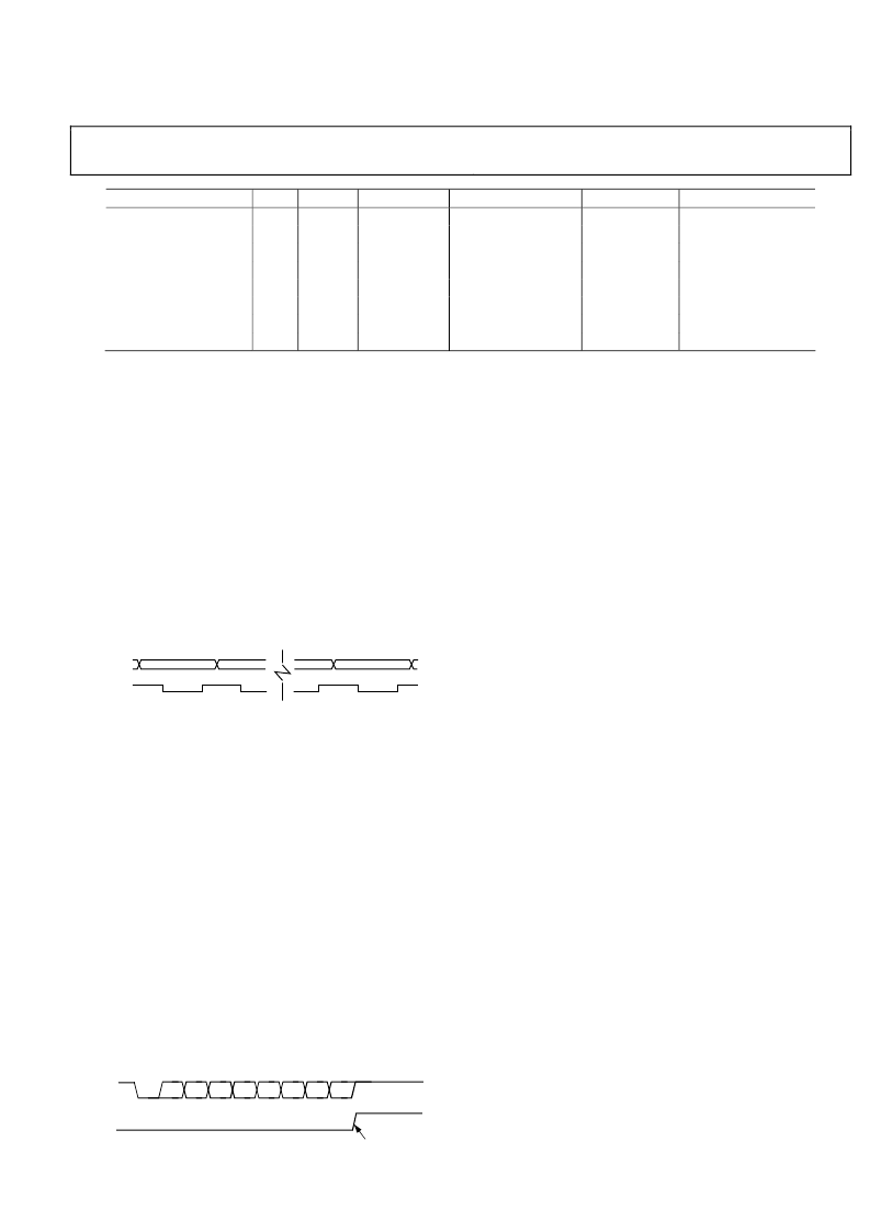
Transmission is initiated by a write to SBUF. Next a stop bit (a
1) is loaded into the 9th bit position of the transmit shift
register. The data is output bit-by-bit until the stop bit appears
on TxD and the transmit interrupt flag (TI) is automatically set
as shown in Figure 77.
Figure 77. 8-Bit Variable Baud Rate
Reception is initiated when a 1-to-0 transition is detected on
RxD. Assuming that a valid start bit is detected, character
reception continues. The 8 data bits are clocked into the serial
port shift register.
All of the following conditions must be met at the time the final
shift pulse is generated to receive a character:
If the extended UART is disabled (EXTEN=0 in the CFG
SFR), RI must be zero to receive a character. This ensures
that the data in SBUF will not be overwritten if the last
received character has not been read.
If frame error checking is enabled by setting SM2, the
received stop bit must be set to receive a character. This
ensures that every character received comes from a valid
frame, with both a start and a stop bit)
If any of these conditions are
not
met, the received frame is
irretrievably lost, and the receive interrupt flag, RI, is not set.
If the received frame has met the above criteria, the following
events occur:
The 8 bits in the receive shift register are latched into SBUF.
The 9th bit (stop bit) is clocked into RB8 in SCON.
Mode 2 (9- bit UART with baud fixed at F
core
/64
or F
core
/32)
Mode 2 is selected by setting SM0 and clearing SM1. In this
mode, the UART operates in 9-bit mode with a fixed baud rate.
The baud rate is fixed at F
core
/64 by default, although by setting
the SMOD bit in PCON, the frequency can be doubled to
F
core
/32. Eleven bits are transmitted or received: a start bit (0), 8
data bits, a programmable 9th bit, and a stop bit (1). The 9th bit
is most often used as a parity bit or as part of a multiprocessor
communication protocol, although it can be used for anything,
including a ninth data bit if required.
The receiver interrupt flag (RI) is set.
To use the 9
th
data bit as part of a communication protocol for a
TxD
TI
(SCON.1)
START
BIT
D0
D1
D2
D3
D4
D5
D6
D7
STOP BIT
I.E., RSET INTERRUPT
0
相關(guān)PDF資料 |
PDF描述 |
|---|---|
| ADE7169ASTF16-RL | Single-Phase Energy Measurement IC with 8052 MCU, RTC and LCD driver |
| ADE7169ASTZF16 | Single-Phase Energy Measurement IC with 8052 MCU, RTC and LCD driver |
| ADE7169ASTZF16-RL | Single-Phase Energy Measurement IC with 8052 MCU, RTC and LCD driver |
| ADE7169F16 | Single-Phase Energy Measurement IC with 8052 MCU, RTC and LCD driver |
| ADE7751 | Energy Metering IC with On-Chip Fault Detection |
相關(guān)代理商/技術(shù)參數(shù) |
參數(shù)描述 |
|---|---|
| ADE7169ASTF16-RL | 制造商:AD 制造商全稱:Analog Devices 功能描述:Single-Phase Energy Measurement IC with 8052 MCU, RTC and LCD driver |
| ADE7169ASTZF16 | 功能描述:IC ENERGY METER 1PHASE 64LQFP RoHS:是 類別:集成電路 (IC) >> PMIC - 能量測量 系列:- 產(chǎn)品培訓(xùn)模塊:Lead (SnPb) Finish for COTS Obsolescence Mitigation Program 標(biāo)準(zhǔn)包裝:2,500 系列:* |
| ADE7169ASTZF16-RL | 功能描述:IC ENERGY METER 1PHASE 64LQFP RoHS:是 類別:集成電路 (IC) >> PMIC - 能量測量 系列:- 產(chǎn)品培訓(xùn)模塊:Lead (SnPb) Finish for COTS Obsolescence Mitigation Program 標(biāo)準(zhǔn)包裝:2,500 系列:* |
| ADE7169F16 | 制造商:AD 制造商全稱:Analog Devices 功能描述:Single-Phase Energy Measurement IC with 8052 MCU, RTC and LCD driver |
| ADE75 | 制造商:AD 制造商全稱:Analog Devices 功能描述:Single-Phase Energy Measurement IC with 8052 MCU, RTC and LCD driver |
發(fā)布緊急采購,3分鐘左右您將得到回復(fù)。