- 您現(xiàn)在的位置:買賣IC網(wǎng) > PDF目錄20620 > AC244026 (Microchip Technology)EXTENSION PAK PIC16F727-ICE PDF資料下載
參數(shù)資料
| 型號(hào): | AC244026 |
| 廠商: | Microchip Technology |
| 文件頁(yè)數(shù): | 199/274頁(yè) |
| 文件大?。?/td> | 0K |
| 描述: | EXTENSION PAK PIC16F727-ICE |
| 標(biāo)準(zhǔn)包裝: | 1 |
| 類型: | 調(diào)試程序 |
| 適用于相關(guān)產(chǎn)品: | PIC16F727 |
| 所含物品: | 2 個(gè)板 |
第1頁(yè)第2頁(yè)第3頁(yè)第4頁(yè)第5頁(yè)第6頁(yè)第7頁(yè)第8頁(yè)第9頁(yè)第10頁(yè)第11頁(yè)第12頁(yè)第13頁(yè)第14頁(yè)第15頁(yè)第16頁(yè)第17頁(yè)第18頁(yè)第19頁(yè)第20頁(yè)第21頁(yè)第22頁(yè)第23頁(yè)第24頁(yè)第25頁(yè)第26頁(yè)第27頁(yè)第28頁(yè)第29頁(yè)第30頁(yè)第31頁(yè)第32頁(yè)第33頁(yè)第34頁(yè)第35頁(yè)第36頁(yè)第37頁(yè)第38頁(yè)第39頁(yè)第40頁(yè)第41頁(yè)第42頁(yè)第43頁(yè)第44頁(yè)第45頁(yè)第46頁(yè)第47頁(yè)第48頁(yè)第49頁(yè)第50頁(yè)第51頁(yè)第52頁(yè)第53頁(yè)第54頁(yè)第55頁(yè)第56頁(yè)第57頁(yè)第58頁(yè)第59頁(yè)第60頁(yè)第61頁(yè)第62頁(yè)第63頁(yè)第64頁(yè)第65頁(yè)第66頁(yè)第67頁(yè)第68頁(yè)第69頁(yè)第70頁(yè)第71頁(yè)第72頁(yè)第73頁(yè)第74頁(yè)第75頁(yè)第76頁(yè)第77頁(yè)第78頁(yè)第79頁(yè)第80頁(yè)第81頁(yè)第82頁(yè)第83頁(yè)第84頁(yè)第85頁(yè)第86頁(yè)第87頁(yè)第88頁(yè)第89頁(yè)第90頁(yè)第91頁(yè)第92頁(yè)第93頁(yè)第94頁(yè)第95頁(yè)第96頁(yè)第97頁(yè)第98頁(yè)第99頁(yè)第100頁(yè)第101頁(yè)第102頁(yè)第103頁(yè)第104頁(yè)第105頁(yè)第106頁(yè)第107頁(yè)第108頁(yè)第109頁(yè)第110頁(yè)第111頁(yè)第112頁(yè)第113頁(yè)第114頁(yè)第115頁(yè)第116頁(yè)第117頁(yè)第118頁(yè)第119頁(yè)第120頁(yè)第121頁(yè)第122頁(yè)第123頁(yè)第124頁(yè)第125頁(yè)第126頁(yè)第127頁(yè)第128頁(yè)第129頁(yè)第130頁(yè)第131頁(yè)第132頁(yè)第133頁(yè)第134頁(yè)第135頁(yè)第136頁(yè)第137頁(yè)第138頁(yè)第139頁(yè)第140頁(yè)第141頁(yè)第142頁(yè)第143頁(yè)第144頁(yè)第145頁(yè)第146頁(yè)第147頁(yè)第148頁(yè)第149頁(yè)第150頁(yè)第151頁(yè)第152頁(yè)第153頁(yè)第154頁(yè)第155頁(yè)第156頁(yè)第157頁(yè)第158頁(yè)第159頁(yè)第160頁(yè)第161頁(yè)第162頁(yè)第163頁(yè)第164頁(yè)第165頁(yè)第166頁(yè)第167頁(yè)第168頁(yè)第169頁(yè)第170頁(yè)第171頁(yè)第172頁(yè)第173頁(yè)第174頁(yè)第175頁(yè)第176頁(yè)第177頁(yè)第178頁(yè)第179頁(yè)第180頁(yè)第181頁(yè)第182頁(yè)第183頁(yè)第184頁(yè)第185頁(yè)第186頁(yè)第187頁(yè)第188頁(yè)第189頁(yè)第190頁(yè)第191頁(yè)第192頁(yè)第193頁(yè)第194頁(yè)第195頁(yè)第196頁(yè)第197頁(yè)第198頁(yè)當(dāng)前第199頁(yè)第200頁(yè)第201頁(yè)第202頁(yè)第203頁(yè)第204頁(yè)第205頁(yè)第206頁(yè)第207頁(yè)第208頁(yè)第209頁(yè)第210頁(yè)第211頁(yè)第212頁(yè)第213頁(yè)第214頁(yè)第215頁(yè)第216頁(yè)第217頁(yè)第218頁(yè)第219頁(yè)第220頁(yè)第221頁(yè)第222頁(yè)第223頁(yè)第224頁(yè)第225頁(yè)第226頁(yè)第227頁(yè)第228頁(yè)第229頁(yè)第230頁(yè)第231頁(yè)第232頁(yè)第233頁(yè)第234頁(yè)第235頁(yè)第236頁(yè)第237頁(yè)第238頁(yè)第239頁(yè)第240頁(yè)第241頁(yè)第242頁(yè)第243頁(yè)第244頁(yè)第245頁(yè)第246頁(yè)第247頁(yè)第248頁(yè)第249頁(yè)第250頁(yè)第251頁(yè)第252頁(yè)第253頁(yè)第254頁(yè)第255頁(yè)第256頁(yè)第257頁(yè)第258頁(yè)第259頁(yè)第260頁(yè)第261頁(yè)第262頁(yè)第263頁(yè)第264頁(yè)第265頁(yè)第266頁(yè)第267頁(yè)第268頁(yè)第269頁(yè)第270頁(yè)第271頁(yè)第272頁(yè)第273頁(yè)第274頁(yè)
PIC16F72X/PIC16LF72X
DS41341E-page 30
2009 Microchip Technology Inc.
2.3
PCL and PCLATH
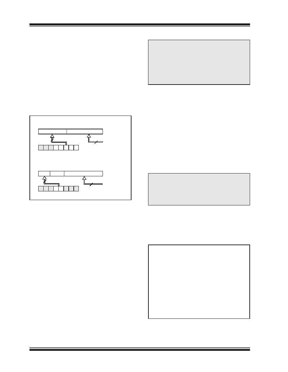
The Program Counter (PC) is 13 bits wide. The low
byte comes from the PCL register, which is a readable
and writable register. The high byte (PC<12:8>) is not
directly
readable
or
writable
and
comes
from
PCLATH. On any Reset, the PC is cleared. Figure 2-7
shows the two situations for the loading of the PC. The
upper example in Figure 2-7 shows how the PC is
loaded on a write to PCL (PCLATH<4:0>
→ PCH).
The lower example in Figure 2-7 shows how the PC is
loaded
during
a
CALL
or
GOTO
instruction
(PCLATH<4:3>
→ PCH).
FIGURE 2-7:
LOADING OF PC IN
DIFFERENT SITUATIONS
2.3.1
COMPUTED GOTO
A computed GOTO is accomplished by adding an offset
to the program counter (ADDWF PCL). When perform-
ing a table read using a computed GOTO method, care
should be exercised if the table location crosses a PCL
memory boundary (each 256-byte block). Refer to the
Application Note AN556, “Implementing a Table Read”
(DS00556).
2.3.2
STACK
All devices have an 8-level x 13-bit wide hardware
not part of either program or data space and the Stack
Pointer is not readable or writable. The PC is PUSHed
onto the stack when a CALL instruction is executed or
an interrupt causes a branch. The stack is POPed in
the event of a RETURN, RETLW or a RETFIE instruction
execution. PCLATH is not affected by a PUSH or POP
operation.
The stack operates as a circular buffer. This means that
after the stack has been PUSHed eight times, the ninth
PUSH overwrites the value that was stored from the
first PUSH. The tenth PUSH overwrites the second
PUSH (and so on).
2.4
Program Memory Paging
All devices are capable of addressing a continuous 8K
word block of program memory. The CALL and GOTO
instructions provide only 11 bits of address to allow
branching within any 2K program memory page. When
doing a CALL or GOTO instruction, the upper 2 bits of
the address are provided by PCLATH<4:3>. When
doing a CALL or GOTO instruction, the user must ensure
that the page select bits are programmed so that the
desired program memory page is addressed. If a return
from a CALL instruction (or interrupt) is executed, the
entire 13-bit PC is POPed off the stack. Therefore,
manipulation of the PCLATH<4:3> bits is not required
for the RETURN instructions (which POPs the address
from the stack).
Example 2-1 shows the calling of a subroutine in
page 1 of the program memory. This example assumes
that PCLATH is saved and restored by the Interrupt
Service Routine (if interrupts are used).
EXAMPLE 2-1:
CALL OF A SUBROUTINE
IN PAGE 1 FROM PAGE 0
PC
12
8
7
0
5
PCLATH<4:0>
PCLATH
Instruction with
ALU Result
GOTO
, CALL
OPCODE<10:0>
8
PC
12
11 10
0
11
PCLATH<4:3>
PCH
PCL
87
2
PCLATH
PCH
PCL
PCL as
Destination
Note 1: There are no Status bits to indicate stack
overflow or stack underflow conditions.
2: There are no instructions/mnemonics
called PUSH or POP. These are actions
that occur from the execution of the CALL,
RETURN
,
RETLW
and RETFIE instruc-
tions or the vectoring to an interrupt
address.
Note:
The contents of the PCLATH register are
unchanged after a RETURN or RETFIE
instruction is executed. The user must
rewrite the contents of the PCLATH regis-
ter for any subsequent subroutine calls or
GOTO
instructions.
ORG 500h
PAGESEL SUB_P1
;Select page 1
;(800h-FFFh)
CALL
SUB1_P1 ;Call subroutine in
:
;page 1 (800h-FFFh)
:
ORG
900h
;page 1 (800h-FFFh)
SUB1_P1
:
;called subroutine
;page 1 (800h-FFFh)
:
RETURN
;return to
;Call subroutine
;in page 0
;(000h-7FFh)
相關(guān)PDF資料 |
PDF描述 |
|---|---|
| ISL6610IBZ-T | IC MOSFET DRVR DUAL SYNC 14-SOIC |
| C1005C0G1H080C | CAP CER 8PF 50V NP0 0402 |
| F931V475MCC | CAP TANT 4.7UF 35V 20% 2312 |
| ADE7759ARS | IC ENERGY METERING 1PHASE 20SSOP |
| GBM25DSUI | CONN EDGECARD 50POS DIP .156 SLD |
相關(guān)代理商/技術(shù)參數(shù) |
參數(shù)描述 |
|---|---|
| AC244027 | 功能描述:插座和適配器 Processor Ext Pak (PIC16LF727-ICE)200K RoHS:否 制造商:Silicon Labs 產(chǎn)品:Adapter 用于:EM35x |
| AC244028 | 功能描述:插座和適配器 Processor Ext Pak for PIC24F16KA102 RoHS:否 制造商:Silicon Labs 產(chǎn)品:Adapter 用于:EM35x |
| AC244033 | 功能描述:開發(fā)板和工具包 - PIC / DSPIC PIC18F14K22-ICE Processor Ext Pak RoHS:否 制造商:Microchip Technology 產(chǎn)品:Starter Kits 工具用于評(píng)估:chipKIT 核心:Uno32 接口類型: 工作電源電壓: |
| AC244034 | 功能描述:開發(fā)板和工具包 - PIC / DSPIC PIC18LF14K22-ICE Processor Ext Pak RoHS:否 制造商:Microchip Technology 產(chǎn)品:Starter Kits 工具用于評(píng)估:chipKIT 核心:Uno32 接口類型: 工作電源電壓: |
| AC244035 | 功能描述:開發(fā)板和工具包 - PIC / DSPIC Processor Ext Pak for PIC16F1939 RoHS:否 制造商:Microchip Technology 產(chǎn)品:Starter Kits 工具用于評(píng)估:chipKIT 核心:Uno32 接口類型: 工作電源電壓: |
發(fā)布緊急采購(gòu),3分鐘左右您將得到回復(fù)。