- 您現(xiàn)在的位置:買賣IC網(wǎng) > PDF目錄375133 > A31W33128 (AMIC Technology Corporation) LCD Controller-Driver PDF資料下載
參數(shù)資料
| 型號: | A31W33128 |
| 廠商: | AMIC Technology Corporation |
| 英文描述: | LCD Controller-Driver |
| 中文描述: | LCD控制器驅(qū)動器 |
| 文件頁數(shù): | 14/34頁 |
| 文件大?。?/td> | 359K |
| 代理商: | A31W33128 |
第1頁第2頁第3頁第4頁第5頁第6頁第7頁第8頁第9頁第10頁第11頁第12頁第13頁當前第14頁第15頁第16頁第17頁第18頁第19頁第20頁第21頁第22頁第23頁第24頁第25頁第26頁第27頁第28頁第29頁第30頁第31頁第32頁第33頁第34頁
A31W33128 Series
PRELIMINARY
(December, 2000, Version 0.1)
13
AMIC Technology, Inc
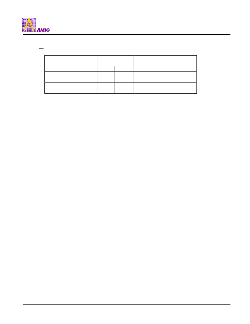
5. Data Bus Select
When
CS
is held at “H” level, the D0-D7 is in high impedance state.
68/80-Series
shared
A0
1
1
0
0
68-Series
80-Series
R/W
1
0
1
0
E
0
1
0
1
R/W
1
0
1
0
Description
Reads from Display Data RAM
Writes to Display Data RAM
Reads Status
Command Write to internal register
6. Display Data RAM
The Display Data RAM is made of dual port RAM. The size of the RAM is 64 x 128 + 128 = 8320 bits.
Write “L” or data to be displayed in all display data RAM before turning the display ON.
7. Accessing the Display Data RAM From MPU
In order to match the operating frequency of Display Data RAM with that of the MPU, a dummy read is required before the
first actual display data read. When the MPU reads the Display Data RAM, the first dummy read cycle stores the first read
data in the bus holder, and then at the next read cycle the MPU read the first read data from the bus holder.
It does not need a dummy cycle when MPU writes data to the Display Data RAM. When the MPU write data to Display Data
RAM, once the data is stored in the bus holder, then it is written to Display Data RAM before the next data write cycle.
8. Set Column Address (higher, lower nibble)
This command specifies the column address (higher and lower nibble) of the Display Data RAM. The column address will be
incremented by each data access after it is pre-set by the MPU.
9. Set Page Address(0-8)
This command positions the page address to 1 of 9 possible positions in Display Data RAM. Page 0-7 are the graphic
display area, and the page 8 are the Icon display area.
10. Set display start line (0-63)
The command is used to change the display page or smooth scroll.
With the display start line value equals to 0, D0 of page 0 is mapped to COM1. The display start line values of 0 to 63 are
assigned to page 0 to 7.
相關(guān)PDF資料 |
PDF描述 |
|---|---|
| A31W33128C | LCD Controller-Driver |
| A31W33128T | LCD Controller-Driver |
| A31W65132 | LCD Controller-Driver |
| A31W65132C | LCD Controller-Driver |
| A31W65132T | LCD Controller-Driver |
相關(guān)代理商/技術(shù)參數(shù) |
參數(shù)描述 |
|---|---|
| A31W33128C | 制造商:AMICC 制造商全稱:AMIC Technology 功能描述:LCD Controller-Driver |
| A31W33128T | 制造商:AMICC 制造商全稱:AMIC Technology 功能描述:LCD Controller-Driver |
| A31W65132 | 制造商:AMICC 制造商全稱:AMIC Technology 功能描述:LCD Controller-Driver |
| A31W65132C | 制造商:AMICC 制造商全稱:AMIC Technology 功能描述:LCD Controller-Driver |
| A31W65132T | 制造商:AMICC 制造商全稱:AMIC Technology 功能描述:LCD Controller-Driver |
發(fā)布緊急采購,3分鐘左右您將得到回復。