- 您現(xiàn)在的位置:買賣IC網(wǎng) > PDF目錄4178 > A1440A-VQG100C (Microsemi SoC)IC FPGA 4K GATES 100-VQFP PDF資料下載
參數(shù)資料
| 型號(hào): | A1440A-VQG100C |
| 廠商: | Microsemi SoC |
| 文件頁數(shù): | 21/90頁 |
| 文件大小: | 0K |
| 描述: | IC FPGA 4K GATES 100-VQFP |
| 產(chǎn)品變化通告: | A1440A Family Discontinuation 24/Jan/2012 |
| 標(biāo)準(zhǔn)包裝: | 90 |
| 系列: | ACT™ 3 |
| LAB/CLB數(shù): | 564 |
| 輸入/輸出數(shù): | 83 |
| 門數(shù): | 4000 |
| 電源電壓: | 4.5 V ~ 5.5 V |
| 安裝類型: | 表面貼裝 |
| 工作溫度: | 0°C ~ 70°C |
| 封裝/外殼: | 100-TQFP |
| 供應(yīng)商設(shè)備封裝: | 100-VQFP(14x14) |
第1頁第2頁第3頁第4頁第5頁第6頁第7頁第8頁第9頁第10頁第11頁第12頁第13頁第14頁第15頁第16頁第17頁第18頁第19頁第20頁當(dāng)前第21頁第22頁第23頁第24頁第25頁第26頁第27頁第28頁第29頁第30頁第31頁第32頁第33頁第34頁第35頁第36頁第37頁第38頁第39頁第40頁第41頁第42頁第43頁第44頁第45頁第46頁第47頁第48頁第49頁第50頁第51頁第52頁第53頁第54頁第55頁第56頁第57頁第58頁第59頁第60頁第61頁第62頁第63頁第64頁第65頁第66頁第67頁第68頁第69頁第70頁第71頁第72頁第73頁第74頁第75頁第76頁第77頁第78頁第79頁第80頁第81頁第82頁第83頁第84頁第85頁第86頁第87頁第88頁第89頁第90頁
Detailed Specifications
2- 20
R e visio n 3
Tightest Delay Distributions
Propagation delay between logic modules depends on the resistive and capacitive loading of the routing
tracks, the interconnect elements, and the module inputs being driven. Propagation delay increases as
the length of routing tracks, the number of interconnect elements, or the number of inputs increases.
From a design perspective, the propagation delay can be statistically correlated or modeled by the fanout
(number of loads) driven by a module. Higher fanout usually requires some paths to have longer lengths
of routing track. The ACT 3 family delivers the tightest fanout delay distribution of any FPGA. This tight
distribution is achieved in two ways: by decreasing the delay of the interconnect elements and by
decreasing the number of interconnect elements per path.
Microsemi’s patented PLICE antifuse offers a very low resistive/capacitive interconnect. The ACT 3
family’s antifuses, fabricated in 0.8 micron m lithography, offer nominal levels of 200
Ω resistance and 6
femtofarad (fF) capacitance per antifuse. The ACT 3 fanout distribution is also tighter than alternative
devices due to the low number of antifuses required per interconnect path. The ACT 3 family’s
proprietary architecture limits the number of antifuses per path to only four, with 90% of interconnects
using only two antifuses.
The ACT 3 family’s tight fanout delay distribution offers an FPGA design environment in which fanout can
be traded for the increased performance of reduced logic level designs. This also simplifies performance
estimates when designing with ACT 3 devices.
Timing Characteristics
Timing characteristics for ACT 3 devices fall into three categories: family dependent, device dependent,
and design dependent. The input and output buffer characteristics are common to all ACT 3 family
members. Internal routing delays are device dependent. Design dependency means actual delays are
not determined until after placement and routing of the user’s design is complete. Delay values may then
be determined by using the ALS Timer utility or performing simulation with post-layout delays.
Critical Nets and Typical Nets
Propagation delays are expressed only for typical nets, which are used for initial design performance
evaluation. Critical net delays can then be applied to the most time-critical paths. Critical nets are
determined by net property assignment prior to placement and routing. Up to 6% of the nets in a design
may be designated as critical, while 90% of the nets in a design are typical.
Long Tracks
Some nets in the design use long tracks. Long tracks are special routing resources that span multiple
rows, columns, or modules. Long tracks employ three and sometimes four antifuse connections. This
increases capacitance and resistance, result ng in longer net delays for macros connected to long tracks.
Typically up to 6% of nets in a fully utilized device require long tracks. Long tracks contribute
approximately 4 ns to 14 ns delay. This additional delay is represented statistically in higher fanout
(FO = 8) routing delays in the datasheet specifications section.
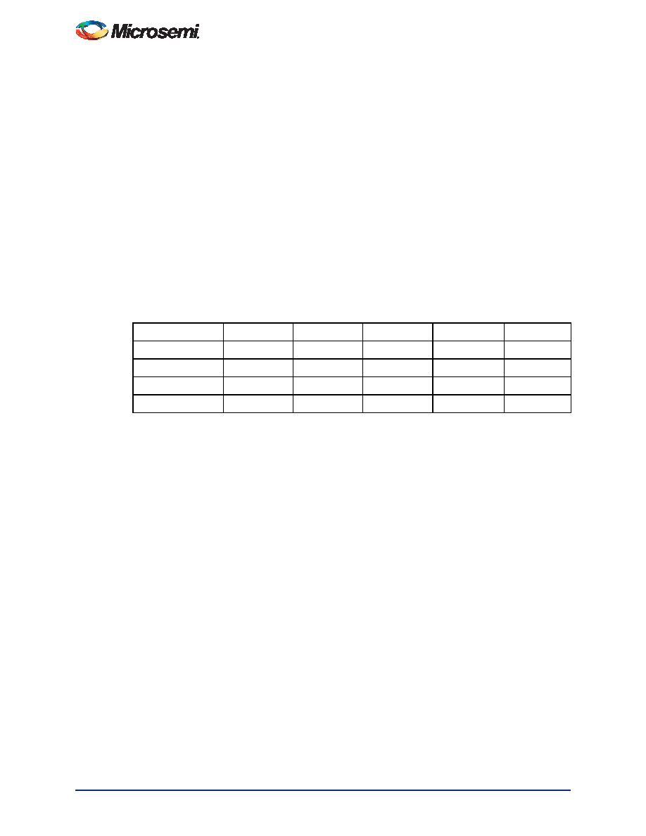
Table 2-14 Logic Module and Routing Delay by Fanout (ns); Worst-Case Commercial Conditions
Speed Grade
FO = 1
FO = 2
FO = 3
FO = 4
FO = 8
ACT 3 –3
2.9
3.2
3.4
3.7
4.8
ACT 3 –2
3.3
3.7
3.9
4.2
5.5
ACT 3 –1
3.7
4.2
4.4
4.8
6.2
ACT 3 STD
4.3
4.8
5.1
5.5
7.2
Notes:
1. Obtained by added tRD(x=FO) to tPD from the Logic Module Timing Characteristics Tables found in this
datasheet.
2. The –2 and –3 speed grades have been discontinued. Refer to
相關(guān)PDF資料 |
PDF描述 |
|---|---|
| A14V25A-PLG84C | IC FPGA 2500 GATES 3.3V 84-PLCC |
| A1440A-PLG84C | IC FPGA 4K GATES 84-PLCC |
| A14V25A-PL84C | IC FPGA 2500 GATES 3.3V 84-PLCC |
| A1425A-1PL84C | IC FPGA 2500 GATES 84-PLCC |
| FMC26DRYH-S13 | CONN EDGECARD 52POS .100 EXTEND |
相關(guān)代理商/技術(shù)參數(shù) |
參數(shù)描述 |
|---|---|
| A1440A-VQG100I | 功能描述:IC FPGA 4K GATES 100-VQFP RoHS:是 類別:集成電路 (IC) >> 嵌入式 - FPGA(現(xiàn)場可編程門陣列) 系列:ACT™ 3 產(chǎn)品變化通告:XC4000(E,L) Discontinuation 01/April/2002 標(biāo)準(zhǔn)包裝:24 系列:XC4000E/X LAB/CLB數(shù):100 邏輯元件/單元數(shù):238 RAM 位總計(jì):3200 輸入/輸出數(shù):80 門數(shù):3000 電源電壓:4.5 V ~ 5.5 V 安裝類型:表面貼裝 工作溫度:-40°C ~ 100°C 封裝/外殼:120-BCBGA 供應(yīng)商設(shè)備封裝:120-CPGA(34.55x34.55) |
| A1441 | 制造商:ALLEGRO 制造商全稱:Allegro MicroSystems 功能描述:Low-Voltage Full-Bridge Brushless DC Motor Driver with Hall Element Commutation |
| A1441_06 | 制造商:ALLEGRO 制造商全稱:Allegro MicroSystems 功能描述:Low-Voltage Full-Bridge Brushless DC Motor Driver with Hall Element Commutation |
| A14410-01 | 功能描述:導(dǎo)熱接口產(chǎn)品 Tflex 620 9x9" 3.0W/mK gap filler RoHS:否 制造商:Panasonic Electronic Components 類型:Thermal Graphite Sheets 材料:Graphite Polymer Film 長度:180 mm 寬度:115 mm 厚度:0.07 mm 工作溫度范圍: |
| A14411-01 | 功能描述:導(dǎo)熱接口產(chǎn)品 Tflex 630 DC1 9x9" 3.0W/mK gap filler RoHS:否 制造商:Panasonic Electronic Components 類型:Thermal Graphite Sheets 材料:Graphite Polymer Film 長度:180 mm 寬度:115 mm 厚度:0.07 mm 工作溫度范圍: |
發(fā)布緊急采購,3分鐘左右您將得到回復(fù)。