- 您現(xiàn)在的位置:買賣IC網(wǎng) > PDF目錄375097 > A1141LUA (Allegro MicroSystems, Inc.) Sensitive Two-Wire Chopper-Stabilized Unipolar Hall-Effect Switches PDF資料下載
參數(shù)資料
| 型號(hào): | A1141LUA |
| 廠商: | Allegro MicroSystems, Inc. |
| 英文描述: | Sensitive Two-Wire Chopper-Stabilized Unipolar Hall-Effect Switches |
| 中文描述: | 敏感的兩線斬波穩(wěn)定單極霍爾效應(yīng)開關(guān) |
| 文件頁數(shù): | 1/11頁 |
| 文件大小: | 393K |
| 代理商: | A1141LUA |
A1140/41/42/43
A1140-DS
Worcester, Massachusetts 01615-0036 (508) 853-5000
www.allegromicro.com
115 Northeast Cutoff, Box 15036
Allegro MicroSystems, Inc.
AB SO LUTE MAX MUM RAT NGS
Supply Voltage, V
CC
..........................................
28 V
Reverse-Supply Voltage, V
RCC
........................
–18 V
Magnetic Flux Density, B.........................
Unlimited
Operating Temperature
Ambient, T
A
, Range E..................
–40oC to 85oC
Ambient, T
A
, Range L................
–40oC to 150oC
Maximum Junction, T
J(max)
........................
165oC
Storage Temperature, T
S
..................
–65oC to 170oC
On-chip protection
y
Supply transient protection
y
Reverse-battery protection
y
On-board voltage regulator
y
3.5 V to 24 V operation
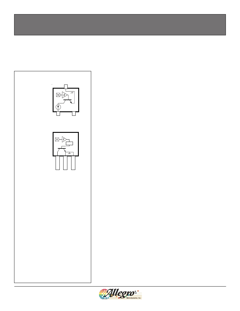
Sensitive Two-Wire Chopper-Stabilized
Unipolar Hall-Effect Switches
Package LH, 3-pin SOT
Features and Bene
fi
ts
1. VCC
2. No connection
3. GND
The A1140, A1141, A1142, and A1143 devices are sensitive, two-wire, unipo-
lar, Hall effect switches that are factory-programmed at end-of-line to optimize
magnetic switchpoint accuracy. These devices are produced on the Allegro
MicroSystems advanced BiCMOS wafer fabrication process, which implements a
patented, high-frequency, chopper-stabilization technique that achieves magnetic
stability and eliminates the offsets that are inherent in single-element devices
exposed to harsh application environments. Commonly found in a number of
automotive applications, the A1140-43 family of devices are utilized to sense: seat
track position, seat belt buckle presence, hood/trunk latching, and shift selector
position.
Two-wire unipolar switches are particularly advantageous in price-sensitive appli-
cations, because they require one less wire than the more traditional open-collec-
tor output switches. Additionally, the system designer gains inherent diagnostics
because output current normally
fl
ows in either of two narrowly-speci
fi
ed ranges.
Any output current level outside of these two ranges is a fault condition. The
A1140-43 family of devices also features on-chip transient protection, and a Zener
clamp to protect against overvoltage conditions on the supply line.
The output currents of the A1141 and A1143 switch
HIGH
in the presence of a south
polarity magnetic
fi
eld of suf
fi
cient strength; and switch
LOW
otherwise, including
when there is no signi
fi
cant magnetic
fi
eld present. The A1140 and A1142 have
inverted output current levels: switching
LOW
in the presence of a south polarity
magnetic
fi
eld of suf
fi
cient strength, and
HIGH
otherwise. The devices also differ in
their speci
fi
ed
LOW
current supply levels.
All family members are offered in two package styles: SOT-23W, a miniature low-
pro
fi
le package for surface-mount applications (suf
fi
x
–LH
), and TO-92, three-
lead ultra-mini Single Inline Package (SIP) for through-hole mounting
(suf
fi
x
–UA
).
Field-programmable versions are also available. Refer to: A1180, A1181, A1182,
and A1183.
NC
1
2
3
PTCT
1
2
3
1. VCC
2. GND
3. GND
Package UA, 3-pin SIP
Chopper stabilization
y
Low switchpoint drift over operating tem-
perature range
y
Low stress sensitivity
Factory programmed at end-of-line for
optimized switchpoints
相關(guān)PDF資料 |
PDF描述 |
|---|---|
| A1143LUA | Sensitive Two-Wire Chopper-Stabilized Unipolar Hall-Effect Switches |
| A1143EUA | Sensitive Two-Wire Chopper-Stabilized Unipolar Hall-Effect Switches |
| A1143LLH | Sensitive Two-Wire Chopper-Stabilized Unipolar Hall-Effect Switches |
| A1140 | Sensitive Two-Wire Chopper-Stabilized Unipolar Hall-Effect Switches |
| A1140LLH | Sensitive Two-Wire Chopper-Stabilized Unipolar Hall-Effect Switches |
相關(guān)代理商/技術(shù)參數(shù) |
參數(shù)描述 |
|---|---|
| A1141LUATI-T4 | 制造商:ALLEGRO 制造商全稱:Allegro MicroSystems 功能描述:Sensitive Two-Wire Chopper-Stabilized Unipolar Hall Effect Switches |
| A1141U2N2NZNQ | 功能描述:旋鈕開關(guān) SP 90 DEG. 2 POS RoHS:否 制造商:C&K Components 位置數(shù)量:5 卡片組數(shù)量: 每卡片組極數(shù):2 電流額定值:250 mA 電壓額定值:125 V 指數(shù)角: 觸點(diǎn)類型: 觸點(diǎn)形式:DPST 端接類型:Solder 安裝類型:Panel 觸點(diǎn)電鍍:Silver |
| A1142 | 制造商:HAKKO Corporation 功能描述: |
| A11421100 | 制造商:LAMB INDUSTRIES 功能描述: |
| A1142B | 功能描述:NOZZLE,BENT,SINGLE,1.5 X 3MM,FR- 制造商:american hakko products, inc. 系列:* 零件狀態(tài):在售 標(biāo)準(zhǔn)包裝:1 |
發(fā)布緊急采購,3分鐘左右您將得到回復(fù)。