- 您現(xiàn)在的位置:買賣IC網(wǎng) > PDF目錄50397 > 93MT120KPBF (VISHAY INTERTECHNOLOGY INC) 1200 V, SCR PDF資料下載
參數(shù)資料
| 型號(hào): | 93MT120KPBF |
| 廠商: | VISHAY INTERTECHNOLOGY INC |
| 元件分類: | 晶閘管 |
| 英文描述: | 1200 V, SCR |
| 封裝: | ROHS COMPLIANT, INT-A-PAK-12 |
| 文件頁(yè)數(shù): | 7/9頁(yè) |
| 文件大小: | 182K |
| 代理商: | 93MT120KPBF |
Document Number: 94353
For technical questions, contact: indmodules@vishay.com
www.vishay.com
Revision: 13-Aug-08
7
5.MT...KPbF, 9.MT...KPbF, 11.MT...KPbF Series
Three Phase Controlled Bridge
(Power Modules), 55 A to 110 A
Vishay High Power Products
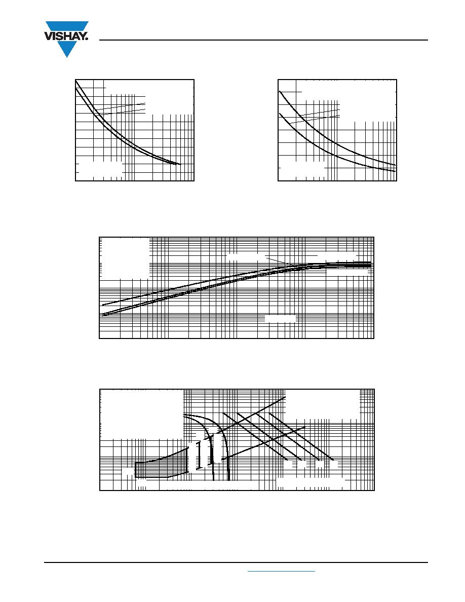
Fig. 14 - Maximum Non-Repetitive Surge Current
Fig. 15 - Maximum Non-Repetitive Surge Current
Fig. 16 - Thermal Impedance ZthJC Characteristics
Fig. 17 - Gate Characteristics
Peak
Half
S
ine
Wave
On-
S
tate
Current
(A)
Number of Equal Amplitude Half
Cycle Current Pulses (N)
10
100
1
At any rated load condition and with
rated V
RRM applied following surge.
94353_14
11.MT..K Series
Per junction
1000
400
700
500
800
600
900
Initial T
J = 125 °C
at 60 Hz 0.0083 s
at 50 Hz 0.0100 s
Peak
Half
S
ine
Wave
On-
S
tate
Current
(A)
Pulse Train Duration (s)
0.01
0.1
1.0
Initial T
J = 125 °C
No voltage reapplied
Rated V
RRM reapplied
Maximum non-repetitive surge current
versus pulse train duration. Control
of conduction may not be maintained.
11.MT..K Series
Per junction
1200
1000
400
94353_15
600
500
800
1100
700
900
0.001
0.01
0.1
1
10
0.001
94353_16
0.01
0.1
1
Square Wave Pulse Duration (s)
Z
thJC
-
Transient
Thermal
Impe
d
ance
(K/W)
10
Per junction
5.MT..K Series
11.MT..K Series
9.MT..K Series
Steady state value
R
thJC = 1.07 K/W
R
thJC = 0.86 K/W
R
thJC = 0.70 K/W
(DC operation)
0.01
94353_17
0.1
1
10
0.001
0.01
0.1
1
Instantaneous Gate Current (A)
Instantaneous
G
ate
Volta
g
e
(V)
1000
100
10
(b)
(a)
(4)
(3)
(2)
(1)
T
J =
-40
°C
T
J =
25
°C
T
J =
125
°C
V
GD
I
GD
Frequency Limited by P
G(AV)
5.MT...K, 9.MT...K, 11.MT...K Series
Rectangular gate pulse
a) Recommended load line for
rated dI/dt: 20 V, 30
Ω;
t
r = 0.5 μs, tp ≥ 6 μs
b) Recommended load line for
≤ 30 % rated dI/dt: 20 V, 65
Ω
t
r = 1 μs, tp ≥ 6 μs
(1) P
GM = 100 W, tp = 500 μs
(2) P
GM = 50 W, tp = 1 ms
(3) P
GM = 20 W, tp = 25 ms
(4) P
GM = 10 W, tp = 5 ms
相關(guān)PDF資料 |
PDF描述 |
|---|---|
| 93MT120KS90PBF | 1200 V, SCR |
| 93MT140KPBF | 1400 V, SCR |
| 93MT140KS90PBF | 1400 V, SCR |
| 93MT160KPBF | 1600 V, SCR |
| 93MT160KS90PBF | 1600 V, SCR |
相關(guān)代理商/技術(shù)參數(shù) |
參數(shù)描述 |
|---|---|
| 93MT120KS90PBF | 制造商:VISHAY 制造商全稱:Vishay Siliconix 功能描述:Three Phase Controlled Bridge (Power Modules), 55 A to 110 A |
| 93MT140K | 制造商:未知廠家 制造商全稱:未知廠家 功能描述:THYRISTOR MODULE|3-PH FULL-WAVE|FULLY CNTLD|1.4KV V(RRM)|90A I(T) |
| 93MT140KB | 制造商:IRF 制造商全稱:International Rectifier 功能描述:THREE PHASE CONTROLLED BRIDGE |
| 93MT140KBS90 | 制造商:IRF 制造商全稱:International Rectifier 功能描述:THREE PHASE CONTROLLED BRIDGE |
| 93MT140KPBF | 制造商:VISHAY 制造商全稱:Vishay Siliconix 功能描述:Three Phase Controlled Bridge (Power Modules), 55 A to 110 A |
發(fā)布緊急采購(gòu),3分鐘左右您將得到回復(fù)。