- 您現(xiàn)在的位置:買賣IC網(wǎng) > PDF目錄36341 > 935270946115 (NXP SEMICONDUCTORS) 1-CHANNEL POWER SUPPLY SUPPORT CKT, PDSO5 PDF資料下載
參數(shù)資料
| 型號: | 935270946115 |
| 廠商: | NXP SEMICONDUCTORS |
| 元件分類: | 電源管理 |
| 英文描述: | 1-CHANNEL POWER SUPPLY SUPPORT CKT, PDSO5 |
| 封裝: | 1.50 MM, PLASTIC, SOT-23, SOT-25, SO-5 |
| 文件頁數(shù): | 12/24頁 |
| 文件大?。?/td> | 238K |
| 代理商: | 935270946115 |
Philips Semiconductors
Product data
SA56615-XX;
SA56616-XX
CMOS system reset with adjustable delay time
2
2002 Mar 25
853–2332 27919
GENERAL DESCRIPTION
The SA56616-XX and SA56615-XX CMOS system resets have low
consumption current of typically 1.0
A and high precision detection
voltage within
±2%. The delay time is adjusted by an external
capacitor working in conjunction with the on-chip delay network. The
SA56615-XX and SA56616-XX have different output configurations
to accommodate a wide variety of microprocessors and logic
devices. The SA56615-XX incorporates a low side open-drain
output topology which requires a pull-up resistor to VDD, while the
SA56616-XX incorporates an active push-pull totem pole output
topology comprised of complimentary P-channel and N-channel
FETs.
The resets operate over a wide operating supply voltage range from
0.7 V to 10 V. Reset detection voltages are available at 0.9 V, 1.8 V,
1.9 V, 2.0 V, 2.7 V, 2.8 V, 2.9 V, 3.0 V, 3.1 V, 4.2 V, 4.3 V, 4.4 V,
4.5 V, 4.6 V and 4.7 V. Other thresholds are offered upon request at
100 mV increments from 0.9 V to 6.0 V. The device comes in the
small SOT23-5 package.
FEATURES
Super low supply current: typically 1.0 A (V
DD = VS + 1 V)
Operating supply voltage range: 0.7 V to 10 V
High precision detection voltage: ±2%
Detection voltage: 0.9 V, 1.8 V, 1.9 V, 2.0 V, 2.7 V, 2.8 V, 2.9 V,
3.0 V, 3.1 V, 4.2 V, 4.3 V, 4.4 V, 4.5 V, 4.6 V, and 4.7 V
Other detection threshold voltages available at 100 mV steps from
0.9 V to 6.0 V
User adjustable reset delay time
Versatile output configurations:
– SA56615-XX:
open-drain
– SA56616-XX:
N-channel/P-channel push-pull
APPLICATIONS
Microprocessor and logic circuit reset
Battery voltage level detection
Battery backup and switching circuits
Adjustable time delay circuits
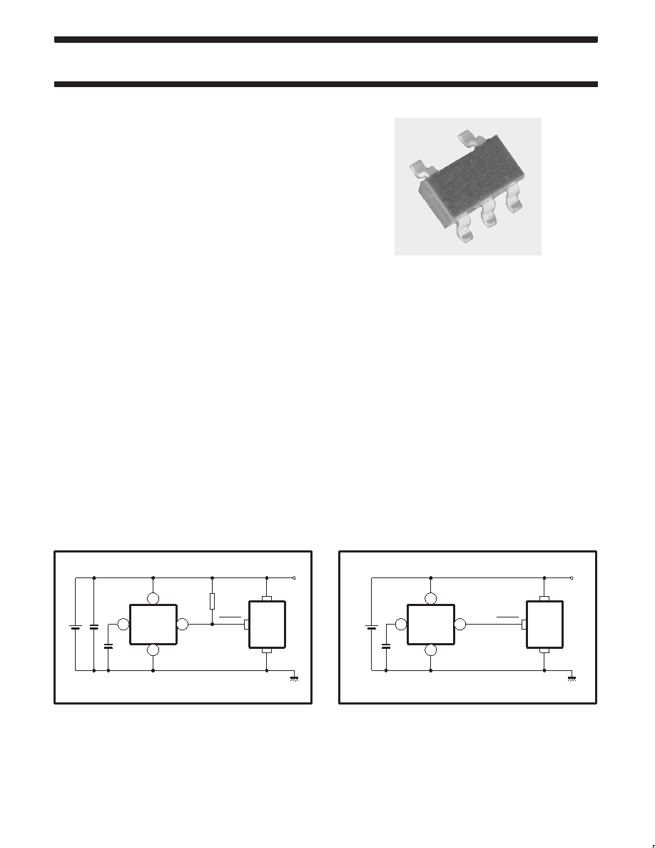
SIMPLIFIED SYSTEM DIAGRAMS
VIN
2
1
3
5
SA56615-XX
OUT
GND
CD
VDD
LOGIC
SYSTEM
RESET
VDD
SL01596
RPU
Figure 1. SA56615-XX simplified system diagram.
SL01597
VIN
2
1
3
5
SA56616-XX
OUT
GND
CD
VDD
LOGIC
SYSTEM
RESET
VDD
Figure 2. SA56616-XX simplified system diagram.
相關(guān)PDF資料 |
PDF描述 |
|---|---|
| 935270943115 | 1-CHANNEL POWER SUPPLY SUPPORT CKT, PDSO5 |
| 935270935115 | 1-CHANNEL POWER SUPPLY SUPPORT CKT, PDSO5 |
| 935270956115 | 1-CHANNEL POWER SUPPLY SUPPORT CKT, PDSO5 |
| 935270955115 | 1-CHANNEL POWER SUPPLY SUPPORT CKT, PDSO5 |
| 935270957115 | 1-CHANNEL POWER SUPPLY SUPPORT CKT, PDSO5 |
相關(guān)代理商/技術(shù)參數(shù) |
參數(shù)描述 |
|---|---|
| 935271394518 | 制造商:NXP Semiconductors 功能描述:IC MCU ARM 20TSSOP |
| 935271933518 | 制造商:NXP Semiconductors 功能描述:IC D-TYPE POS TRG DUAL 56VFBGA |
| 935271933551 | 制造商:NXP Semiconductors 功能描述:IC D-TYPE POS TRG DUAL 56VFBGA |
| 935271933557 | 制造商:NXP Semiconductors 功能描述:IC D-TYPE POS TRG DUAL 56VFBGA |
| 935271937518 | 制造商:NXP Semiconductors 功能描述:IC BUFF DVR TRI-ST 16BIT 56VFBGA |
發(fā)布緊急采購,3分鐘左右您將得到回復(fù)。