- 您現(xiàn)在的位置:買賣IC網 > PDF目錄24814 > 935264471557 (NXP SEMICONDUCTORS) TELEPHONE SPEECH CKT, PQFP44 PDF資料下載
參數(shù)資料
| 型號: | 935264471557 |
| 廠商: | NXP SEMICONDUCTORS |
| 元件分類: | 無繩電話/電話 |
| 英文描述: | TELEPHONE SPEECH CKT, PQFP44 |
| 封裝: | PLASTIC, SOT-307, QFP-44 |
| 文件頁數(shù): | 38/39頁 |
| 文件大?。?/td> | 205K |
| 代理商: | 935264471557 |
第1頁第2頁第3頁第4頁第5頁第6頁第7頁第8頁第9頁第10頁第11頁第12頁第13頁第14頁第15頁第16頁第17頁第18頁第19頁第20頁第21頁第22頁第23頁第24頁第25頁第26頁第27頁第28頁第29頁第30頁第31頁第32頁第33頁第34頁第35頁第36頁第37頁當前第38頁第39頁
1999 Apr 08
8
Philips Semiconductors
Product specication
Speech and loudspeaker amplier IC with
auxiliary inputs/outputs and analog multiplexer
TEA1097
The preferred value for RSLPE is 20 . Changing this value
will affect more than the DC characteristics; it also
influences the transmit gains to the line, the gain control
characteristic, the sidetone level and the maximum output
swing on the line.
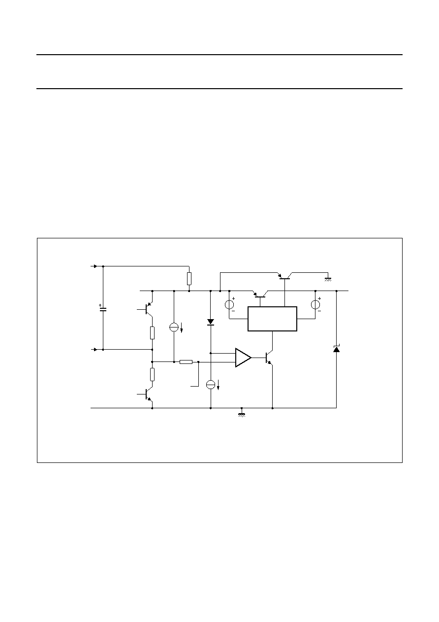
As can be seen from Fig.4, the internal circuitry is supplied
by pin VBB, which is a strong supply point combined with
the line interface. The line current is flowing through the
RSLPE resistor and is sunk by the VBB voltage stabilizer,
becoming available for a loudspeaker amplifier or any
peripheral IC. Its voltage is equal to 3.0 V for line currents
lower than 18 mA. It than increases linearly with the line
current and reaches the value of 5.3 V for line currents
greater than 45 mA. It is temperature compensated.
The aim of the current switch TR1 and TR2 is to reduce
distortion of large AC line signals. Current ISLPE is supplied
to VBB via TR1 when the voltage on SLPE is greater than
VBB + 0.25 V. When the voltage on SLPE is lower than this
value, the current ISLPE is shunted to GND via TR2.
The reference voltage Vref can be increased by connecting
an external resistor between pins REG and SLPE.
For large line currents, this increase can slightly affect
some dynamic performances such as maximum signal
level on the line for 2% THD. The voltage on pin VBB is not
affected by this external resistor. See Fig.5 for the main
DC voltages.
Fig.4 Line interface principle.
handbook, full pagewidth
MGM298
TN2
TR2
TR1
E2
D1
R3
R2
R1
TN1
TP1
J2
J1
E1
GND
VBB
from
preamp
GND
REG
LN
SLPE
CREG
4.7
F
RSLPE
20
相關PDF資料 |
PDF描述 |
|---|---|
| 935264477112 | TELEPHONE SPEECH CKT, PDSO40 |
| 935264477118 | TELEPHONE SPEECH CKT, PDSO40 |
| 08-350000-11-RC | SOCKET ADAPTR SOIC/8PIN .300 DIP |
| 08-3518-00 | PRAEZISIONSSOCKEL S518 8POL |
| 08-350000-10 | ADAPTER SOIC/DIL 8POL |
相關代理商/技術參數(shù) |
參數(shù)描述 |
|---|---|
| 935267356112 | 制造商:NXP Semiconductors 功能描述:IC TEA1507PN |
| 935268081112 | 制造商:NXP Semiconductors 功能描述:SUB ONLY IC |
| 935268721125 | 制造商:NXP Semiconductors 功能描述:Buffer/Line Driver 1-CH Non-Inverting 3-ST CMOS 5-Pin TSSOP T/R |
| 935269304128 | 制造商:ST-Ericsson 功能描述:IC AUDIO CODEC W/TCH SCRN 48LQFP |
| 935269544557 | 制造商:NXP Semiconductors 功能描述:SUB ONLY TDA9587-2US1-V1.3 |
發(fā)布緊急采購,3分鐘左右您將得到回復。