- 您現(xiàn)在的位置:買賣IC網(wǎng) > PDF目錄24812 > 935263812118 (NXP SEMICONDUCTORS) QUAD 1-BIT TRANSCEIVER, TRUE OUTPUT, PDSO16 PDF資料下載
參數(shù)資料
| 型號(hào): | 935263812118 |
| 廠商: | NXP SEMICONDUCTORS |
| 元件分類: | 總線收發(fā)器 |
| 英文描述: | QUAD 1-BIT TRANSCEIVER, TRUE OUTPUT, PDSO16 |
| 封裝: | PLASTIC, SOT-403, TSSOP-16 |
| 文件頁數(shù): | 7/11頁 |
| 文件大?。?/td> | 88K |
| 代理商: | 935263812118 |
Philips Semiconductors
Product specification
GTL2004
Quad GTL/GTL+ to LVTTL/TTL
bidirectional latched translator
2000 Jun 19
5
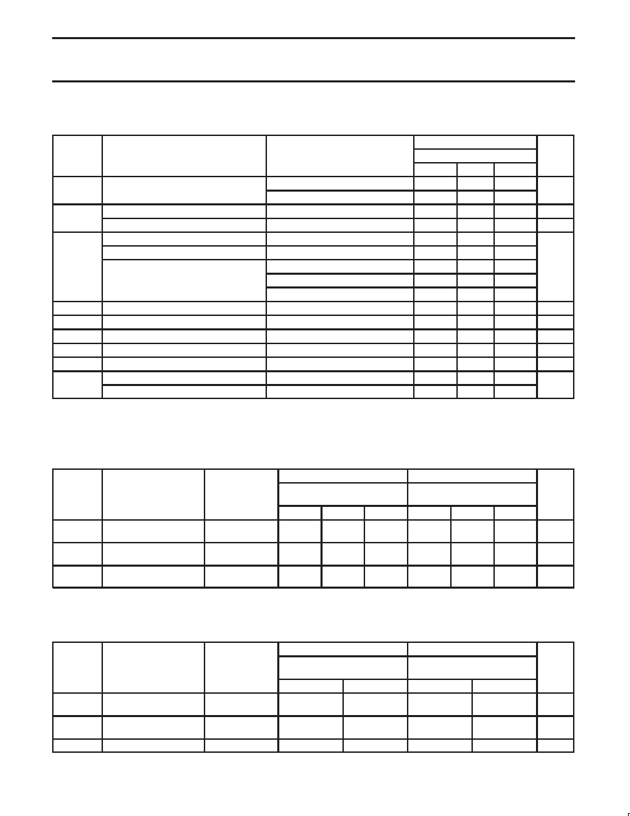
DC ELECTRICAL CHARACTERISTICS
Over recommended operating conditions. Voltages are referenced to GND (ground = 0 V).
LIMITS
SYMBOL
PARAMETER
TEST CONDITIONS
–40
°C to +85°C
UNIT
MIN
TYP1
MAX
VO
B port
VCC = 3.0 to 3.6 V; IOH = –100 A
VCC–0.2
V
VOH
B port
VCC = 3.0 V; IOH = –12 mA
2.0
V
VO
A port
VCC = 3.0 V; IOL = 40 mA
0.4
V
VOL
B port
VCC = 3.0 V; IOL = 12 mA
0.8
V
Control inputs
VCC = 3.6 V; VI = VCC or GND
± 1
A port
VCC = 3.6 V; VI = VTT or GND
± 1
II
VCC = 0 or 3.6 V; VI = 5.5
10
A
B port
VCC = 3.6 V; VI = VCC
± 1
VCC = 3.6 V; VI = 0 V
–5
IOFF
A port
VCC = 0 V;VI or VO = 0 to 4.5 V
± 100
A
IEX
B port
VO = 5.5 V; VCC = 3.0 V
50
125
A
ICC
A or B port
VCC = 3.6 V;VI = VCC or GND; IO = 0
3
mA
ICC3
B port or control inputs
VCC = 3.6 V; VI = VCC –0.6 V
500
A
CI
Control inputs
VI = 3.0 V or 0
3
pF
C O
B port
VO = 3.0 V or 0
7.2
pF
CIO
A port
VO = VTT or 0
4.6
pF
NOTES:
1. All typical values are measured at VCC = 3.3 V and Tamb = 25°C.
2. The input and output voltage ratings may be exceeded if the input and output current ratings are observed.
3. This is the increase in supply current for each input that is at the specified TTL voltage level rather than VCC or GND.
AC CHARACTERISTICS (3.3 V
"0.3 V RANGE)
LIMITS (GTL)
LIMITS (GTL+)
SYMBOL
PARAMETER
WAVEFORM
VCC = 3.3V "0.3V
VREF = 0.8V
VCC = 3.3V "0.3V
VREF = 1.0V
UNIT
MIN
TYP1
MAX
MIN
TYP1
MAX
tPLH
tPHL
Bn to An
2
2.0
1.8
2.8
2.5
2.0
1.8
2.8
2.5
ns
tPLH
tPHL
An to Bn
3
4.4
4.7
6.5
5.8
4.4
4.5
5.7
5.1
ns
tPLH
tPHL
LEn to Bn
1
3.5
3.4
4.9
4.2
3.5
3.4
4.9
4.2
ns
NOTE:
1. All typical values are at VCC = 3.3 V and Tamb = 25°C.
AC SETUP REQUIREMENT (3.3 V
"0.3 V RANGE)
Over recommended ranges of supply voltage.1
LIMITS (GTL)
LIMITS (GTL+)
SYMBOL
PARAMETER
WAVEFORM
VCC = 3.3V "0.3V
VREF = 0.8V
VCC = 3.3V "0.3V
VREF = 1.0V
UNIT
MIN
MAX
MIN
MAX
tS(H)
tS(L)
Setup time (An to LEn)
4
1.3
1.5
1.2
1.5
ns
th(H)
th(L)
Hold time (An to LEn)
4
0.0
ns
tw(H)
LEn pulse width
3
1.1
ns
NOTE:
1. These parameters are warranted but not production tested.
相關(guān)PDF資料 |
PDF描述 |
|---|---|
| 935263835118 | SPECIALTY INTERFACE CIRCUIT, PQFP32 |
| 935263836118 | SPECIALTY INTERFACE CIRCUIT, PQFP32 |
| 935263841026 | SPECIALTY INTERFACE CIRCUIT, UUC40 |
| 935263837118 | SPECIALTY INTERFACE CIRCUIT, PQFP32 |
| 935263838118 | SPECIALTY INTERFACE CIRCUIT, PQFP32 |
相關(guān)代理商/技術(shù)參數(shù) |
參數(shù)描述 |
|---|---|
| 935264217557 | 制造商:NXP Semiconductors 功能描述:SUB ONLY IC |
| 935267356112 | 制造商:NXP Semiconductors 功能描述:IC TEA1507PN |
| 935268081112 | 制造商:NXP Semiconductors 功能描述:SUB ONLY IC |
| 935268721125 | 制造商:NXP Semiconductors 功能描述:Buffer/Line Driver 1-CH Non-Inverting 3-ST CMOS 5-Pin TSSOP T/R |
| 935269304128 | 制造商:ST-Ericsson 功能描述:IC AUDIO CODEC W/TCH SCRN 48LQFP |
發(fā)布緊急采購,3分鐘左右您將得到回復(fù)。