- 您現在的位置:買賣IC網 > PDF目錄48327 > 934054010118 (NXP SEMICONDUCTORS) 5 A, 35 V, SILICON, RECTIFIER DIODE PDF資料下載
參數資料
| 型號: | 934054010118 |
| 廠商: | NXP SEMICONDUCTORS |
| 元件分類: | 整流器 |
| 英文描述: | 5 A, 35 V, SILICON, RECTIFIER DIODE |
| 文件頁數: | 1/7頁 |
| 文件大小: | 67K |
| 代理商: | 934054010118 |
Philips Semiconductors
Product specification
Rectifier diodes
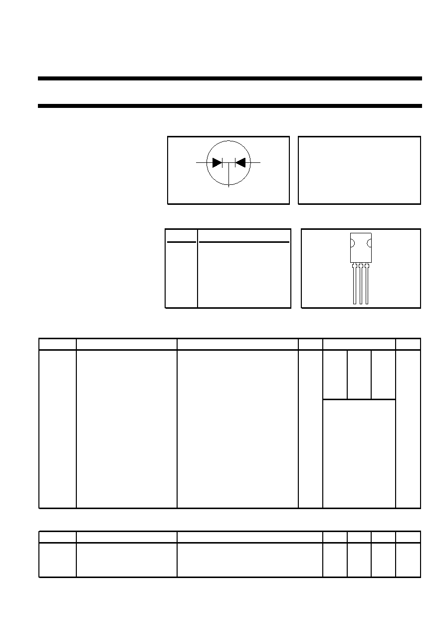
PBYR645CT series
Schottky barrier
FEATURES
SYMBOL
QUICK REFERENCE DATA
Low forward volt drop
Fast switching
V
R = 35 V/ 40 V/ 45 V
Reverse surge capability
High thermal cycling performance
I
O(AV) = 10 A
Low thermal resistance
V
F ≤ 0.6V
GENERAL DESCRIPTION
PINNING
SOT82
Dual, common cathode schottky
PIN
DESCRIPTION
rectifier
diodes
in
a
plastic
envelope. Intended for use as
1
anode 1
output rectifiers in low voltage, high
frequency switched mode power
2
cathode
supplies.
3
anode 2
The PBYR645CT series is supplied
in the conventional leaded SOT82
tab
cathode
package.
LIMITING VALUES
Limiting values in accordance with the Absolute Maximum System (IEC 134)
SYMBOL PARAMETER
CONDITIONS
MIN.
MAX.
UNIT
PBYR6
35CT 40CT 45CT
V
RRM
Peak repetitive reverse
-
35
40
45
V
voltage
V
RWM
Working peak reverse
-
35
40
45
V
voltage
V
R
Continuous reverse voltage
T
mb ≤ 100 C
-
35
40
45
V
I
O(AV)
Average rectified output
square wave;
δ = 0.5; T
mb ≤ 119 C
-
10
A
current (both diodes
conducting)
I
FRM
Repetitive peak forward
square wave;
δ = 0.5; T
mb ≤ 119 C
-
10
A
current per diode
I
FSM
Non-repetitive peak forward
t = 10 ms
-
75
A
current diode
t = 8.3 ms
-
82
A
sinusoidal; T
j = 125 C prior to
surge; with reapplied V
RRM(max)
I
RRM
Peak repetitive reverse
pulse width and repetition rate
-
1
A
surge current per diode
limited by T
j max
T
j
Operating junction
-
150
C
temperature
T
stg
Storage temperature
- 65
150
C
THERMAL RESISTANCES
SYMBOL PARAMETER
CONDITIONS
MIN.
TYP. MAX. UNIT
R
th j-mb
Thermal resistance junction
per diode
-
5
K/W
to mounting base
both diodes
-
4
K/W
R
th j-a
Thermal resistance junction
in free air
-
100
-
K/W
to ambient
k
a1
a2
13
2
1
23
May 1998
1
Rev 1.200
相關PDF資料 |
PDF描述 |
|---|---|
| 934054020118 | 5 A, 40 V, SILICON, RECTIFIER DIODE |
| 934053870127 | 8 A, 200 V, SILICON, RECTIFIER DIODE, TO-220AB |
| 934054000118 | 1.5 A, 40 V, SILICON, RECTIFIER DIODE |
| 934053480118 | 1.5 A, 45 V, SILICON, RECTIFIER DIODE |
| 934054743113 | 0.05 A, 3000 V, SILICON, SIGNAL DIODE |
相關代理商/技術參數 |
參數描述 |
|---|---|
| 934054713215 | 制造商:NXP Semiconductors 功能描述:SUB ONLY TXSTR |
| 934054900215 | 制造商:NXP Semiconductors 功能描述:SUB ONLY TXSTR SGNL |
| 934054930215 | 制造商:NXP Semiconductors 功能描述:Diode Schottky 40V 0.2A 3-Pin TO-236AB T/R |
| 934054945115 | 制造商:NXP Semiconductors 功能描述:Diode Switching 100V 0.25A 2-Pin SOD-323 T/R |
| 934055092127 | 制造商:NXP Semiconductors 功能描述:H-OUT #7460 |
發(fā)布緊急采購,3分鐘左右您將得到回復。