- 您現(xiàn)在的位置:買賣IC網(wǎng) > PDF目錄360489 > 74LV573 (NXP Semiconductors N.V.) Octal D-type transparent latch 3-State PDF資料下載
參數(shù)資料
| 型號: | 74LV573 |
| 廠商: | NXP Semiconductors N.V. |
| 英文描述: | Octal D-type transparent latch 3-State |
| 中文描述: | 八路D型透明鎖存器三態(tài) |
| 文件頁數(shù): | 2/14頁 |
| 文件大?。?/td> | 123K |
| 代理商: | 74LV573 |
Philips Semiconductors
Product specification
74LV573
Octal D-type transparent latch (3-State)
2
1998 Jun 10
853-1989 19545
FEATURES
Wide operating voltage: 1.0 to 5.5V
Optimized for Low Voltage applications: 1.0V to 3.6V
Accepts TTL input levels between V
CC
= 2.7V and V
CC
= 3.6V
Typical V
OLP
(output ground bounce) < 0.8V at V
CC
= 3.3V,
T
amb
= 25
°
C
Typical V
OHV
(output V
OH
undershoot) > 2V at V
CC
= 3.3V,
T
amb
= 25
°
C
Inputs and outputs on opposite sides of package allowing easy
interface with microprocessors
Useful as input or output port for microprocessors/microcomputer
Common 3-State output enable input
Output capability: bus driver
I
CC
category: MSI
DESCRIPTION
The 74LV573 is a low-voltage Si-gate CMOS device that is pin and
function compatible with 74HC/HCT573.
The 74LV573 is an octal D-type transparent latch featuring separate
D-type inputs for each latch and 3-State outputs for bus oriented
applications. A latch enable (LE) input and an output enable (OE)
input are common to all internal latches.
The ‘573’ consists of eight D-type transparent latches with 3-State
true outputs. When LE is HIGH, data at the D
n
inputs enters the
latches. In this condition the latches are transparent, i.e., a latch
output will change each time its corresponding D-input changes.
When LE is LOW the latches store the information that was present
at the D-inputs a set-up time preceding the HIGH-to-LOW transition
of LE. When OE is LOW, the contents of the eight latches are
available at the outputs. When OE is HIGH, the outputs go to the
high impedance OFF-state. Operation of the OE input does not
affect the state of the latches.
The ‘573’ is functionally identical to the ‘563’ and the ‘373’, but the
‘563’ has inverted outputs and the ‘373’ has a different pin
arrangement.
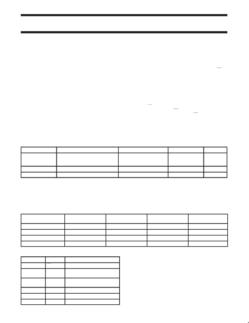
QUICK REFERENCE DATA
GND = 0V; T
amb
= 25
°
C; t
r
= t
f
SYMBOL
2.5 ns
PARAMETER
CONDITIONS
TYPICAL
UNIT
t
PHL
/t
PLH
Propagation delay
Dn to Qn
LE to Qn
C
L
= 15pF
V
CC
= 3.3V
12
13
ns
C
I
C
PD
NOTES:
1. C
PD
is used to determine the dynamic power dissipation (P
D
in
μ
W)
P
D
= C
PD
V
CC2
x f
i
(C
L
f
i
= input frequency in MHz; C
L
= output load capacity in pF;
f
o
= output frequency in MHz; V
= supply voltage in V;
(C
L
V
CC2
f
o
) = sum of the outputs.
2. The condition is V
I
= GND to V
CC.
Input capacitance
3.5
pF
Power dissipation capacitance per latch
Notes 1, 2
26
pF
V
CC2
f
o
) where:
ORDERING AND PACKAGE INFORMATION
PACKAGES
TEMPERATURE RANGE
OUTSIDE NORTH
AMERICA
NORTH AMERICA
PKG. DWG. #
20-Pin Plastic DIL
–40
°
C to +125
°
C
–40
°
C to +125
°
C
–40
°
C to +125
°
C
–40
°
C to +125
°
C
74LV573 N
74LV573 N
SOT146-1
20-Pin Plastic SO
74LV573 D
74LV573 D
SOT163-1
20-Pin Plastic SSOP Type II
74LV573 DB
74LV573 DB
SOT339-1
20-Pin Plastic TSSOP Type I
74LV573 PW
74LV573PW DH
SOT360-1
PIN DESCRIPTION
PIN NUMBER
SYMBOL
FUNCTION
1
OE
Output enabled input (active LOW)
2, 3, 4, 5,
6, 7, 8, 9
D0–D7
Data inputs
19, 18, 17, 16,
15, 14, 13, 12
Q0–Q7
Data outputs
10
GND
Ground (0V)
11
LE
Latch enable input (active HIGH)
20
VCC
Positive supply voltage
相關(guān)PDF資料 |
PDF描述 |
|---|---|
| 74LV573PWDH | Octal D-type transparent latch 3-State |
| 74LV574 | Octal D-type flip-flop; positive edge-trigger 3-State |
| 74LV574PWDH | Octal D-type flip-flop; positive edge-trigger 3-State |
| 74LV595PWDH | 8-bit serial-in/serial or parallel-out shift register with output latches 3-State |
| 74LV595 | 8-bit serial-in/serial or parallel-out shift register with output latches (3-State)(帶輸出鎖存的8位串聯(lián)輸入/串聯(lián)或并聯(lián)輸出移位寄存器(三態(tài))) |
相關(guān)代理商/技術(shù)參數(shù) |
參數(shù)描述 |
|---|---|
| 74LV573A | 制造商:TI 制造商全稱:Texas Instruments 功能描述:OCTAL TRANSPARENT D-TYPE LATCHES WITH 3-STATE OUTPUTS |
| 74LV573D | 制造商:NXP Semiconductors 功能描述:74LV SMD 74LV573 SOIC20 3.3V |
| 74LV573D,112 | 功能描述:閉鎖 OCTAL TRANSPARANT LATCH RoHS:否 制造商:Micrel 電路數(shù)量:1 邏輯類型:CMOS 邏輯系列:TTL 極性:Non-Inverting 輸出線路數(shù)量:9 高電平輸出電流: 低電平輸出電流: 傳播延遲時間: 電源電壓-最大:12 V 電源電壓-最小:5 V 最大工作溫度:+ 85 C 最小工作溫度:- 40 C 封裝 / 箱體:SOIC-16 封裝:Reel |
| 74LV573D,118 | 功能描述:閉鎖 OCTAL TRANSPARANT RoHS:否 制造商:Micrel 電路數(shù)量:1 邏輯類型:CMOS 邏輯系列:TTL 極性:Non-Inverting 輸出線路數(shù)量:9 高電平輸出電流: 低電平輸出電流: 傳播延遲時間: 電源電壓-最大:12 V 電源電壓-最小:5 V 最大工作溫度:+ 85 C 最小工作溫度:- 40 C 封裝 / 箱體:SOIC-16 封裝:Reel |
| 74LV573D | 制造商:NXP Semiconductors 功能描述:IC SM 74LV LOGIC |
發(fā)布緊急采購,3分鐘左右您將得到回復(fù)。