- 您現(xiàn)在的位置:買(mǎi)賣(mài)IC網(wǎng) > PDF目錄360435 > 74F381SJ (FAIRCHILD SEMICONDUCTOR CORP) 4-Bit Arithmetic Logic Unit PDF資料下載
參數(shù)資料
| 型號(hào): | 74F381SJ |
| 廠商: | FAIRCHILD SEMICONDUCTOR CORP |
| 元件分類: | 通用總線功能 |
| 英文描述: | 4-Bit Arithmetic Logic Unit |
| 中文描述: | F/FAST SERIES, 4-BIT ARITHMETIC LOGIC UNIT, PDSO20 |
| 封裝: | 5.30 MM, EIAJ TYPE2, SOP-20 |
| 文件頁(yè)數(shù): | 1/7頁(yè) |
| 文件大小: | 82K |
| 代理商: | 74F381SJ |
Philips Semiconductors
Product specification
74F381
Arithmetic Logic Unit
1
1989 Mar 01
853–0418 95907
FEATURES
Low-input loading minimizes drive requirements
Performs six arithmetic and logic functions
Selectable Low (clear) and High (preset) functions
Carry Generate and Propagate outputs for use with Carry
look-ahead generator
DESCRIPTION
The 74F381 performs three arithmetic and three logic operations on
two 4-bit words, A and B. Three additional Select (S0–S2) input
codes force the Function outputs Low or High. Carry Propagate (P)
and Generate (G) ouputs are provided for use with the 74F182
Carry Look Ahead Generator for high-speed expansion to longer
word lengths. For ripple expansion, refer to the 74F382 ALU data
sheet.
Signals applied to the Select inputs (S0–S2) determine the mode of
operation, as indicated in the Function Select Table. An extensive
listing of input and output function levels is shown in the Function
Table. The circuit performs the arithmetic functions for either
active-HIgh or active-Low operands, with output levels in the same
convention. In the subtract operating modes, it is necessary to force
a Carry (High for active-HIgh operands, Low for active-Low
operands) into the Cn input of the least significant package. The
Carry Generate (G) and Carry Propagate (P) outputs supply input
signals to the 74F182 Carry look-ahead generator for expansion to
longer word length, as shown in Figure 1. Note that a 74F382 ALU is
used for the most significant package. Typical delays for Figure 1
are given in Table 1.
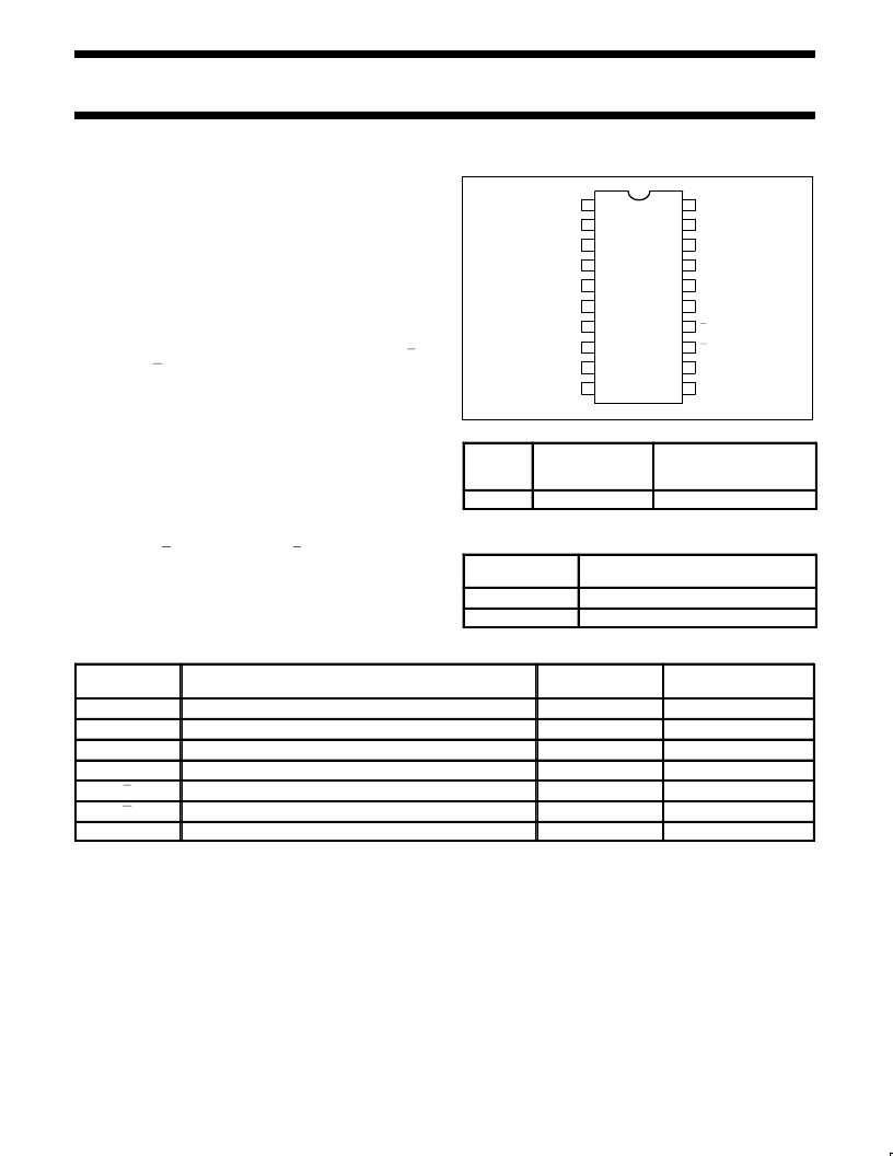
PIN CONFIGURATION
20
19
18
17
16
15
14
7
6
5
4
3
2
1
13
8
V
CC
A1
B1
A0
B0
S0
S1
S2
F0
F1
GND
A2
B2
A3
B3
Cn
P
G
F3
F2
SF00921
12
9
11
10
TYPE
TYPICAL
PROPAGATION
DELAY
TYPICAL SUPPLY
CURRENT (TOTAL)
74F381
6.5ns
59mA
ORDERING INFORMATION
DESCRIPTION
COMMERCIAL RANGE
V
CC
= 5V
±
10%, T
amb
= 0
°
C to +70
°
C
N74F381N
20-pin plastic DIP
20-pin plastic SO
N74F381D
INPUT AND OUTPUT LOADING AND FAN OUT TABLE
PINS
DESCRIPTION
74F (U.L.)
HIGH/LOW
LOAD VALUE
HIGH/LOW
A0 – A3
A operand inputs
1.0/4.0
20
μ
A/2.4mA
20
μ
A/2.4mA
20
μ
A/0.6mA
20
μ
A/2.4mA
B0 – B3
A operand inputs
1.0/4.0
S0 – S2
Function select inputs
1.0/1.0
Cn
Carry input
1.0/4.0
P
Carry Propagate ouptut (active-Low)
50/33
1.0mA/20mA
G
Carry Generate ouptut (active-Low)
50/33
1.0mA/20mA
F0–F3
Outputs
50/33
1.0mA/20mA
NOTE:
One (1.0) FAST unit load is defined as 20
μ
A in the High state and 0.6mA in the Low state.
相關(guān)PDF資料 |
PDF描述 |
|---|---|
| 74F381SCX | Fixed Point ALU |
| 74F381SJX | Fixed Point ALU |
| 74F382 | Arithmetic Logic Unit |
| 74F382 | 4-Bit Arithmetic Logic Unit |
| 74F382PC | 4-Bit Arithmetic Logic Unit |
相關(guān)代理商/技術(shù)參數(shù) |
參數(shù)描述 |
|---|---|
| 74F381SJX | 功能描述:算數(shù)邏輯單元 - ALU 4-Bit Arith Log Unit RoHS:否 制造商:ON Semiconductor 高電平輸出電流: 低電平輸出電流: 傳播延遲時(shí)間: 電源電壓-最大:18 V 電源電壓-最小:3 V 封裝 / 箱體:SOIC-16 Wide 最大工作溫度:+ 125 C 封裝:Reel |
| 74F382 | 制造商:FAIRCHILD 制造商全稱:Fairchild Semiconductor 功能描述:4-Bit Arithmetic Logic Unit |
| 74F382PC | 功能描述:算數(shù)邏輯單元 - ALU 4-Bit Arith Log Unit RoHS:否 制造商:ON Semiconductor 高電平輸出電流: 低電平輸出電流: 傳播延遲時(shí)間: 電源電壓-最大:18 V 電源電壓-最小:3 V 封裝 / 箱體:SOIC-16 Wide 最大工作溫度:+ 125 C 封裝:Reel |
| 74F382SC | 制造商:FAIRCHILD 制造商全稱:Fairchild Semiconductor 功能描述:4-Bit Arithmetic Logic Unit |
| 74F382SCX | 功能描述:算數(shù)邏輯單元 - ALU 4-Bit Arith Log Unit RoHS:否 制造商:ON Semiconductor 高電平輸出電流: 低電平輸出電流: 傳播延遲時(shí)間: 電源電壓-最大:18 V 電源電壓-最小:3 V 封裝 / 箱體:SOIC-16 Wide 最大工作溫度:+ 125 C 封裝:Reel |
發(fā)布緊急采購(gòu),3分鐘左右您將得到回復(fù)。