- 您現(xiàn)在的位置:買賣IC網(wǎng) > PDF目錄91970 > 62CTQ030PBF 30 A, 30 V, SILICON, RECTIFIER DIODE, TO-220AB PDF資料下載
參數(shù)資料
| 型號: | 62CTQ030PBF |
| 元件分類: | 整流器 |
| 英文描述: | 30 A, 30 V, SILICON, RECTIFIER DIODE, TO-220AB |
| 封裝: | TO-220, 3 PIN |
| 文件頁數(shù): | 2/6頁 |
| 文件大?。?/td> | 103K |
| 代理商: | 62CTQ030PBF |
62CTQ030
Bulletin PD-20634 rev. A 12/01
2
www.irf.com
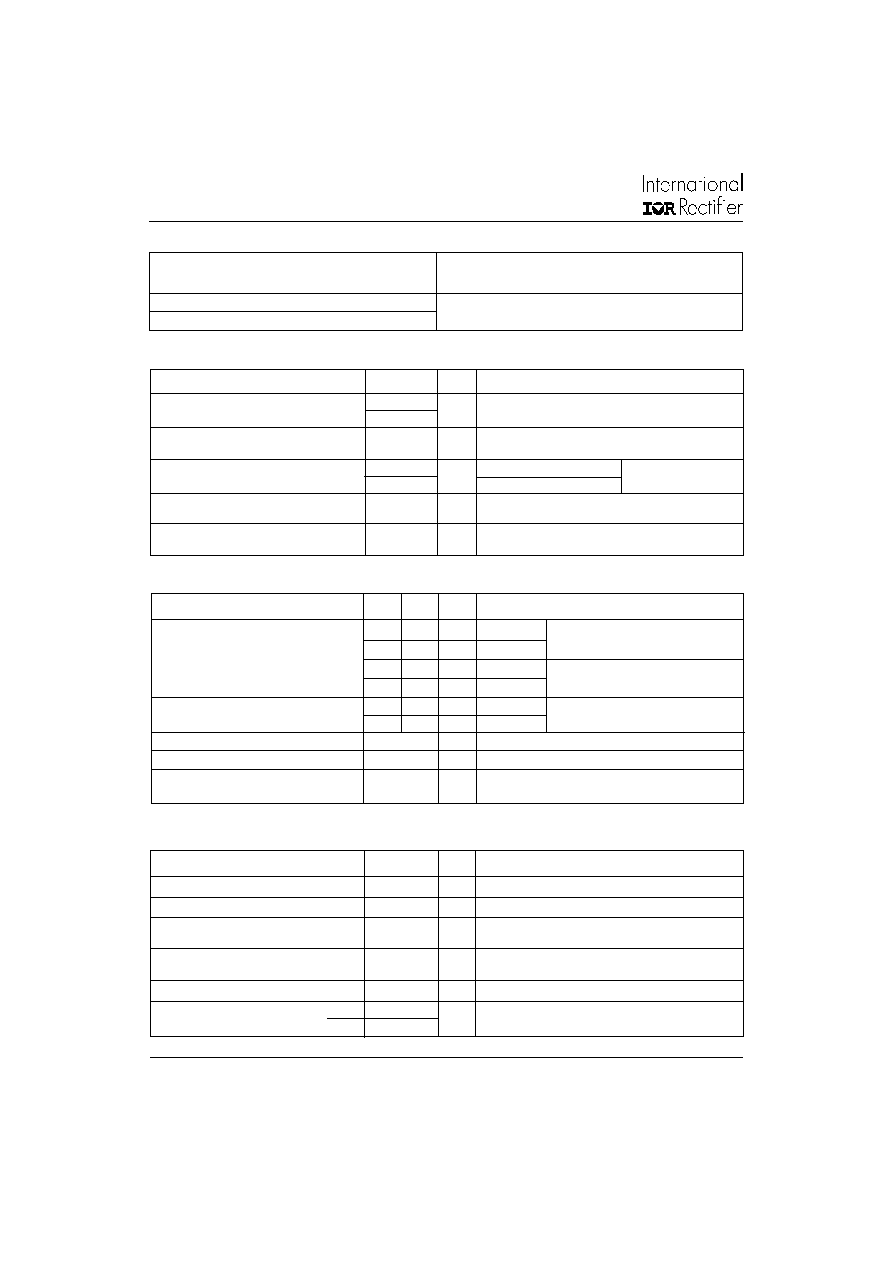
T
J
Max. Junction Temperature Range
-65 to 150
°C
Tstg
Max. Storage Temperature Range
-65 to 175
°C
R
thJC Max. Thermal Resistance
1.2
°C/W DC operation
Junction to Case
(Per Leg)
R
thCS Typical Thermal Resistance
0.50
°C/W Mounting surface, smooth and greased
Case to Heatsink
wt
Approximate Weight
2 (0.07)
g (oz.)
T
Mounting Torque
Min.
6 (5)
Non-lubricated threads
Max.
12 (10)
Thermal-Mechanical Specifications
Parameters
Values
Units Conditions
Kg-cm
(Ibf-in)
I
F(AV) Max. Average Forward (PerLeg)
30
A
50% duty cycle @ T
C = 120°C, rectangular wave form
Current
(Per Device)
60
I
FRM
Peak Repetitive Forward
60
A
Rated V
R, square wave, 20kHz
Current
(Per Leg)
TC =127°C
I
FSM
Max.PeakOneCycleNon-Repetitive
1500
A
5sSineor3sRect.pulse
Surge Current
(Per Leg)
300
10msSineor6msRect.pulse
E
AS
Non-RepetitiveAvalancheEnergy
13
mJ
T
J = 25°C, IAS = 3Amps, L = 2.9mH
(Per Leg)
I
AR
Repetitive Avalanche Current
3
A
Current decaying linearty to zero in 1 sec
(Per Leg)
Frequency limited by TJ max. VA = 1.5 x VR typical
Absolute Maximum Ratings
Parameters
Values
Units Conditions
Following any rated load
condition and with rated
VRRM applied
62CTQ030
VR
Max. DC Reverse Voltage (V)
VRWM Max. Working Peak Reverse Voltage (V)
30
Voltage Ratings
Parameters
V
FM
Max. Forward Voltage Drop
0.46
0.5
V
@ 30A
TJ = 25 °C
0.56
0.6
V
@ 60A
(1)
0.39
0.44
V
@ 30A
T
J = 125 °C
0.54
0.59
V
@ 60A
I
RM
Max. Instantaneus Reverse Current
0.4
2.5
mA
TJ = 25 °C
Rated DC voltage
180
350
mA
TJ = 125 °C
CT
Max. Junction Capacitance
3000
pF
VR = 5VDC (test signal range 100Khz to 1Mhz) 25°C
LS
Typical Series Inductance
8.0
nH
Measured from top of terminal to mounting plane
dv/dt Max. Voltage Rate of Change
10000
V/ s
(Rated VR)
Electrical Specifications
Parameters
Typ. Max. Units Conditions
(1) Pulse Width < 300s, Duty Cycle <2%
相關(guān)PDF資料 |
PDF描述 |
|---|---|
| 62GB-10A | ALUMINUM, FEMALE; MALE, MIL SERIES CONNECTOR, SOLDER, RECEPTACLE |
| 62GB-10E | ALUMINUM, FEMALE; MALE, MIL SERIES CONNECTOR, SOLDER, RECEPTACLE |
| 62GB-10F | ALUMINUM, FEMALE; MALE, MIL SERIES CONNECTOR, SOLDER, RECEPTACLE |
| 62GB-10J | ALUMINUM, FEMALE; MALE, MIL SERIES CONNECTOR, SOLDER, RECEPTACLE |
| 62GB-10P | ALUMINUM, FEMALE; MALE, MIL SERIES CONNECTOR, SOLDER, RECEPTACLE |
相關(guān)代理商/技術(shù)參數(shù) |
參數(shù)描述 |
|---|---|
| 62CTQ030PBF_09 | 制造商:VISHAY 制造商全稱:Vishay Siliconix 功能描述:Schottky Rectifier, 2 x 30 A |
| 62CXX | 制造商:3M 制造商全稱:3M Electronics 功能描述:Eurosocket Type C |
| 62CY1515007 | 制造商:Grayhill 功能描述:- Bulk |
| 62CY2222063 | 制造商:Grayhill 功能描述: |
| 62CY3018001 | 制造商:Grayhill 功能描述:- Bulk |
發(fā)布緊急采購,3分鐘左右您將得到回復(fù)。