- 您現(xiàn)在的位置:買賣IC網(wǎng) > PDF目錄44549 > 5962-9687901QEA (NATIONAL SEMICONDUCTOR CORP) 2.6 A SWITCHING REGULATOR, 173 kHz SWITCHING FREQ-MAX, CDIP16 PDF資料下載
參數(shù)資料
| 型號: | 5962-9687901QEA |
| 廠商: | NATIONAL SEMICONDUCTOR CORP |
| 元件分類: | 穩(wěn)壓器 |
| 英文描述: | 2.6 A SWITCHING REGULATOR, 173 kHz SWITCHING FREQ-MAX, CDIP16 |
| 封裝: | CERAMIC, DIP-16 |
| 文件頁數(shù): | 15/33頁 |
| 文件大小: | 1016K |
| 代理商: | 5962-9687901QEA |
第1頁第2頁第3頁第4頁第5頁第6頁第7頁第8頁第9頁第10頁第11頁第12頁第13頁第14頁當(dāng)前第15頁第16頁第17頁第18頁第19頁第20頁第21頁第22頁第23頁第24頁第25頁第26頁第27頁第28頁第29頁第30頁第31頁第32頁第33頁
Application Information (Continued)
but with copper areas greater than approximately 3 in
2, only
small improvements in heat dissipation are realized. If fur-
ther thermal improvements are needed, double sided or mul-
tilayer PC-board with large copper areas are recommended.
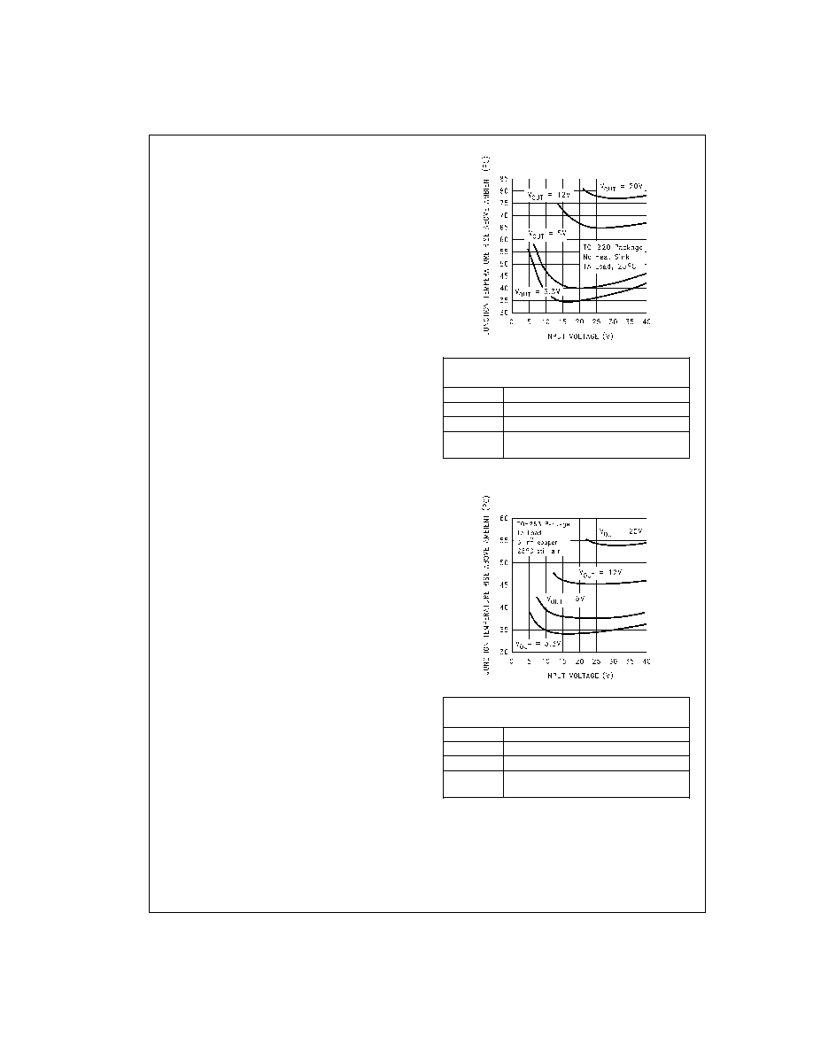
The curves shown in
Figure 20 show the LM2595S (TO-263
package) junction temperature rise above ambient tempera-
ture with a 1A load for various input and output voltages. This
data was taken with the circuit operating as a buck switching
regulator with all components mounted on a PC board to
simulate the junction temperature under actual operating
conditions. This curve can be used for a quick check for the
approximate junction temperature for various conditions, but
be aware that there are many factors that can affect the junc-
tion temperature.
For the best thermal performance, wide copper traces and
generous amounts of printed circuit board copper should be
used in the board layout. (One exception to this is the output
(switch) pin, which should not have large areas of copper.)
Large areas of copper provide the best transfer of heat
(lower thermal resistance) to the surrounding air, and moving
air lowers the thermal resistance even further.
Package thermal resistance and junction temperature rise
numbers are all approximate, and there are many factors
that will affect these numbers. Some of these factors include
board size, shape, thickness, position, location, and even
board temperature. Other factors are, trace width, total
printed circuit copper area, copper thickness, single- or
double-sided, multilayer board and the amount of solder on
the board. The effectiveness of the PC board to dissipate
heat also depends on the size, quantity and spacing of other
components on the board, as well as whether the surround-
ing air is still or moving. Furthermore, some of these compo-
nents such as the catch diode will add heat to the PC board
and the heat can vary as the input voltage changes. For the
inductor, depending on the physical size, type of core mate-
rial and the DC resistance, it could either act as a heat sink
taking heat away from the board, or it could add heat to the
board.
DS012565-34
Circuit Data for Temperature Rise Curve
TO-220 Package (T)
Capacitors
Through hole electrolytic
Inductor
Through hole, Schott, 68 H
Diode
Through hole, 3A 40V, Schottky
PC board
3 square inches single sided 2 oz. copper
(0.0028")
FIGURE 19. Junction Temperature Rise, TO-220
DS012565-35
Circuit Data for Temperature Rise Curve
TO-263 Package (S)
Capacitors
Surface mount tantalum, molded “D” size
Inductor
Surface mount, Schott, 68 H
Diode
Surface mount, 3A 40V, Schottky
PC board
3 square inches single sided 2 oz. copper
(0.0028")
FIGURE 20. Junction Temperature Rise, TO-263
www.national.com
22
相關(guān)PDF資料 |
PDF描述 |
|---|---|
| 5962-9650301QEA | 2.6 A SWITCHING REGULATOR, 173 kHz SWITCHING FREQ-MAX, CDIP16 |
| 5962-9650401QEA | 2.6 A SWITCHING REGULATOR, 173 kHz SWITCHING FREQ-MAX, CDIP16 |
| LM2595J-3.3-QML | 2.6 A SWITCHING REGULATOR, 173 kHz SWITCHING FREQ-MAX, CDIP16 |
| LM2595-5.0MDC | 2.6 A SWITCHING REGULATOR, 173 kHz SWITCHING FREQ-MAX, UUC |
| LM2595-5.0MWC | 2.6 A SWITCHING REGULATOR, 173 kHz SWITCHING FREQ-MAX, UUC |
相關(guān)代理商/技術(shù)參數(shù) |
參數(shù)描述 |
|---|---|
| 5962-9688101Q2A | 制造商:Texas Instruments 功能描述:Comparator Dual 8V 20-Pin LCCC Tube |
| 5962-9688201Q2A | 制造商:Texas Instruments 功能描述:Comparator Quad 8V 20-Pin LCCC Tube 制造商:Rochester Electronics LLC 功能描述:- Bulk 制造商:Texas Instruments 功能描述:COMPARATOR 4 8V 20LCCC - Rail/Tube |
| 5962-9688201QCA | 制造商:Texas Instruments 功能描述:Comparator Quad 8V 14-Pin CDIP Tube 制造商:Rochester Electronics LLC 功能描述:- Bulk |
| 5962-9688201QDA | 制造商:Texas Instruments 功能描述:Comparator Quad 8V 14-Pin CFPAK Tube 制造商:Rochester Electronics LLC 功能描述:- Bulk |
| 5962-9688601QRA | 制造商:Texas Instruments 功能描述:ADC Single SAR 66ksps 12-bit Serial 20-Pin CDIP Tube 制造商:Texas Instruments 功能描述:ADC SGL SAR 66KSPS 12-BIT SERL 20CDIP - Rail/Tube |
發(fā)布緊急采購,3分鐘左右您將得到回復(fù)。