- 您現(xiàn)在的位置:買賣IC網(wǎng) > PDF目錄360262 > 595D156X96R3A2T KONDENSATOR TANTAL SMD 15UF 6.3V PDF資料下載
參數(shù)資料
| 型號(hào): | 595D156X96R3A2T |
| 英文描述: | KONDENSATOR TANTAL SMD 15UF 6.3V |
| 中文描述: | KONDENSATOR鉭貼片15UF 6.3V的 |
| 文件頁(yè)數(shù): | 7/7頁(yè) |
| 文件大?。?/td> | 85K |
| 代理商: | 595D156X96R3A2T |
52
T Y PE 595D
GUIDE T O APPLICAT ION
1.
A-C Ripple Current:
The maximum allowable ripple
current shall be determined from the formula:
where,
P
= Power Dissipation in Watts @ + 25
°
C as
given in the table in Paragraph Number 5
(Power Dissipation).
R
ESR
= The capacitor Equivalent Series Resistance
at the specified frequency.
2.
A-C Ripple Voltage:
The maximum allowable ripple
voltage shall be determined from the formula:
or, from the formula:
V
rms
= I
rms
x Z
where,
P
= Power Dissipation in Watts @ + 25
°
C as
given in the table in Paragraph Number 5
(Power Dissipation).
R
ESR
= The capacitor Equivalent Series Resistance
at the specified frequency.
Z
= The capacitor Impedance at the specified
frequency.
2.1
The sum of the peak AC voltage plus the DC voltage
shall not exceed the DC voltage rating of the capacitor.
2.2
The sum of the negative peak AC voltage plus the
applied DC voltage shall not allow a voltage reversal
exceeding 10% of the DC working voltage at + 25
°
C.
3.
Reverse Voltage:
These capacitors are capable of
withstanding peak voltages in the reverse direction
equal to 10% of the DC rating at + 25
°
C and 5% of the
DC rating at + 85
°
C.
4.
Temperature Derating:
If these capacitors are to be
operated at temperatures above + 25
°
C, the
permissible rms ripple current or voltage shall be
calculated using the derating factors as shown:
P
R
ESR
I
rms
=
Z
V
rms
=
P
R
ESR
T
A
B
C
D
R
Maximum Permissible
Power Dissipation
@ + 25
°
C (Watts)
in free air
Case
Code
6.
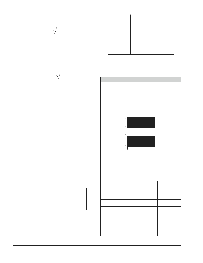
Recommended Mounting Pad Geometries:
The
nib must have sufficient clearance to avoid electrical
contact with other components. The width dimension
indicated is the same as the maximum width of the
capacitor. This is to minimize lateral movement.
Derating
Factor
1.0
0.9
0.8
0.4
Temperature
+ 25
°
C
+ 55
°
C
+ 85
°
C
+ 125
°
C
5.
Power Dissipation:
Power dissipation will be
affected by the heat sinking capability of the mounting
surface. Non-sinusoidal ripple current may produce
heating effects which differ from those shown. It is
important that the equivalent Irmsvalue be
established when calculating permissible operating
levels. (Power dissipation calculated using + 25
°
C
temperature rise.)
[Numbers in brackets indicate millimeters]
* Pads for B, C and D case codes are otherwise pad compatible with
*
Type 293D, B, C and D case codes respectively.
REFLOW S OLDER PADS *
WIDTH
(A)
.055
[1.5]
.082
[2.1]
.120
[3.0]
.136
[3.5]
.180
[4.6]
.245
[6.3]
PAD
METALLIZATION
(B)
.030
[0.7]
.065
[1.7]
.065
[1.7]
.090
[2.3]
.090
[2.3]
.090
[2.3]
SEPARATION
(C)
.025
[0.6]
.050
[1.3]
.065
[1.7]
.120
[3.1]
.145
[3.7]
.145
[3.7]
CASE
CODE
T
A
B
C
D
R
A
B
B
C
0.030
0.070
0.080
0.110
0.150
0.250
Vishay Sprague
70 Pembroke Road, Concord, NH 03301
Phone
(603) 224-1961
Fax
603-224-1430
Internet
www.vishay.com
Major Vishay Brands
Dale Draloric Foil Resistors Measurements Group Roederstein Sfernice Sprague Thin Film Vitramon
相關(guān)PDF資料 |
PDF描述 |
|---|---|
| 595D157X9016R2T | KONDENSATOR TANTAL SMD 150UF 16V |
| 595D225X9010T2T | KONDENSATOR TANTAL SMD 2.2UF 10V |
| 595D225X9020A2T | KONDENSATOR TANTAL SMD 2.2UF 20V |
| 595D225X9035B2T | KONDENSATOR TANTAL SMD 2.2UF 35V |
| 595D226X9020C2T | KONDENSATOR TANTAL SMD 22UF 20V |
相關(guān)代理商/技術(shù)參數(shù) |
參數(shù)描述 |
|---|---|
| 595D156X96R3A2T | 制造商:Vishay Roederstein 功能描述:CAPACITOR CASE A 15UF 6.3V |
| 595D156X96R3A2W | 功能描述:CAP TANT 15UF 6.3V 10% 1507 RoHS:是 類別:電容器 >> 鉭 系列:TANTAMOUNT® 595D 標(biāo)準(zhǔn)包裝:1,000 系列:TANTAMOUNT® 695D 電容:3.3µF 電壓 - 額定:50V 容差:±20% ESR(等效串聯(lián)電阻):3.2 歐姆 類型:保形涂層 工作溫度:-55°C ~ 125°C 安裝類型:表面貼裝 封裝/外殼:2414(6034 公制) 尺寸/尺寸:0.236" L x 0.135" W(6.00mm x 3.43mm) 高度 - 座高(最大):0.085"(2.16mm) 引線間隔:- 制造商尺寸代碼:F 特點(diǎn):通用 包裝:帶卷 (TR) 壽命@溫度:- |
| 595D157X_004B2T | 制造商:VISHAY 制造商全稱:Vishay Siliconix 功能描述:Solid Tantalum Chip Capacitors TANTAMOUNT? Conformal Coated, Maximum CV |
| 595D157X_004C2T | 制造商:VISHAY 制造商全稱:Vishay Siliconix 功能描述:Solid Tantalum Chip Capacitors TANTAMOUNT? Conformal Coated, Maximum CV |
| 595D157X_010C2T | 制造商:VISHAY 制造商全稱:Vishay Siliconix 功能描述:Solid Tantalum Chip Capacitors TANTAMOUNT? Conformal Coated, Maximum CV |
發(fā)布緊急采購(gòu),3分鐘左右您將得到回復(fù)。