- 您現(xiàn)在的位置:買賣IC網(wǎng) > PDF目錄222496 > 56-E37-014-3-5G (SPECTRUM CONTROL INC) 37 CONTACT(S), MALE, D SUBMINIATURE CONNECTOR, SOLDER PDF資料下載
參數(shù)資料
| 型號: | 56-E37-014-3-5G |
| 廠商: | SPECTRUM CONTROL INC |
| 元件分類: | D-微型連接器 |
| 英文描述: | 37 CONTACT(S), MALE, D SUBMINIATURE CONNECTOR, SOLDER |
| 文件頁數(shù): | 2/4頁 |
| 文件大小: | 158K |
| 代理商: | 56-E37-014-3-5G |
SPECTRUM CONTROL INC. 8031 Avonia Rd. Fairview, PA 16415 Phone: 814-474-2207 Fax: 814-474-2208 Web site: www.spectrumcontrol.com
SPECTRUM CONTROL GmbH Hansastrasse 6 91126 Schwabach, Germany Phone: (49)-9122-795-0 Fax: (49)-9122-795-58
182
Series E (ESD/EFT)
Transient Protected Connectors
Filtered
Connectors
Ordering Information
Example:
56-E04-005-5-T
56
-
E 0
4
-
005
-
5
-
T
Integrated
D-sub
Connectors
Series E
(ESD/EFT)
Connectors
Shell Size/
Number of
Contacts
0- 9 size
1- 15 size
2- 25 size
3- 37 size
Contact Type/Termination
1 - Pin to solder cup
2 - Pin to right angle
3 - Socket to straight PCB
4 - Socket to right angle
5 - Adapter (pin to socket)
6 - Socket to solder cup
7 - Pin to straight PCB
Working
Voltage Code
See table below.
(Use 3-digit
code that
matches your
electrical
requirements)
Mounting or Hardware Options
_- .120 thru-hole and 15" gold
3G - 30" gold
5G - 50" gold
SC and Straight PCBs (only)
TIB - 4-40 thread on rear of flange
TIF - 4-40 thread on front of flange
MIB - M3 thread on rear of flange
GBL6 - for .062" boards
JS - Jack screws
Right Angles and Adapters (only)
_- No GBL attached
GL - Includes grounding board lock
T- 4-40 threads
GB - No board locks
J- Jack screws
M- M3 thread
GJ - GL and jack screws
Footprint
(right angle
connectors
only)
3 - .318"
4 - .405"
5- .590"
This part number represents a Series E connector with a shell size of 9
and a socket to right angle configuration. The maximum working voltage
is 5.5 VDC and the connector has a .590" footprint with 4-40 threads.
Notes: Consult factory for custom capacitance values. Typical leakage at 25°C is <25 A
Maximum leakage 50 A at Vm(DC)
Transient Voltage Protection with Capacitance
Immunity to IEC 61000-4-2 (ESD) up to level 4 and IEC 61000-4-4 (EFT) air and contact discharge specifications.
Max. Working Voltage
Working
Voltage Code
003
005
009
012
014
018
026
030
3.5
5.5
9.0
12.0
14.0
18.0
26.0
30.0
>30.0
2.5
4.0
6.5
9.0
10.0
14.0
20.0
25.0
>25.0
10.0@5A
15.5@5A
20.0@2A
25.0@2A
30.0@5A
40.0@5A
58.0@5A
65.0@2A
120
40
120
100
30
5 (3.7-7.0)
8 (7.1-9.3)
12 (11-14)
16 (14-18.5)
18 (15.9-20.3)
25 (22-28)
34 (29.5-38.5)
42 (37-46)
0.3
0.1
0.3
0.1
2200
1600
450
350
480
450
190
80
Clamp Voltage
8 x 20
s
Peak Current
8 x 20
s
Energy (J)
10 x 100
s
Typical Cap.
pF at 1 MHz
V breakdown
1 ma
VDC
VAC
Please consult factory for availability
Transient Voltage Protection without Significant Capacitance
Immunity to IEC 61000-4-2 (ESD) up to Level 4 air and contact discharge. Excellent for digital, high speed and high frequency signals.
Max. Working
Voltage (V) DC
Working
Voltage Code
P24
24.0
150.0
80.0
<1.0 nA
0.05 pF
Clamp Voltage
Maximum
Leakage (A)
Current
Typical Cap.
at 1 MHz
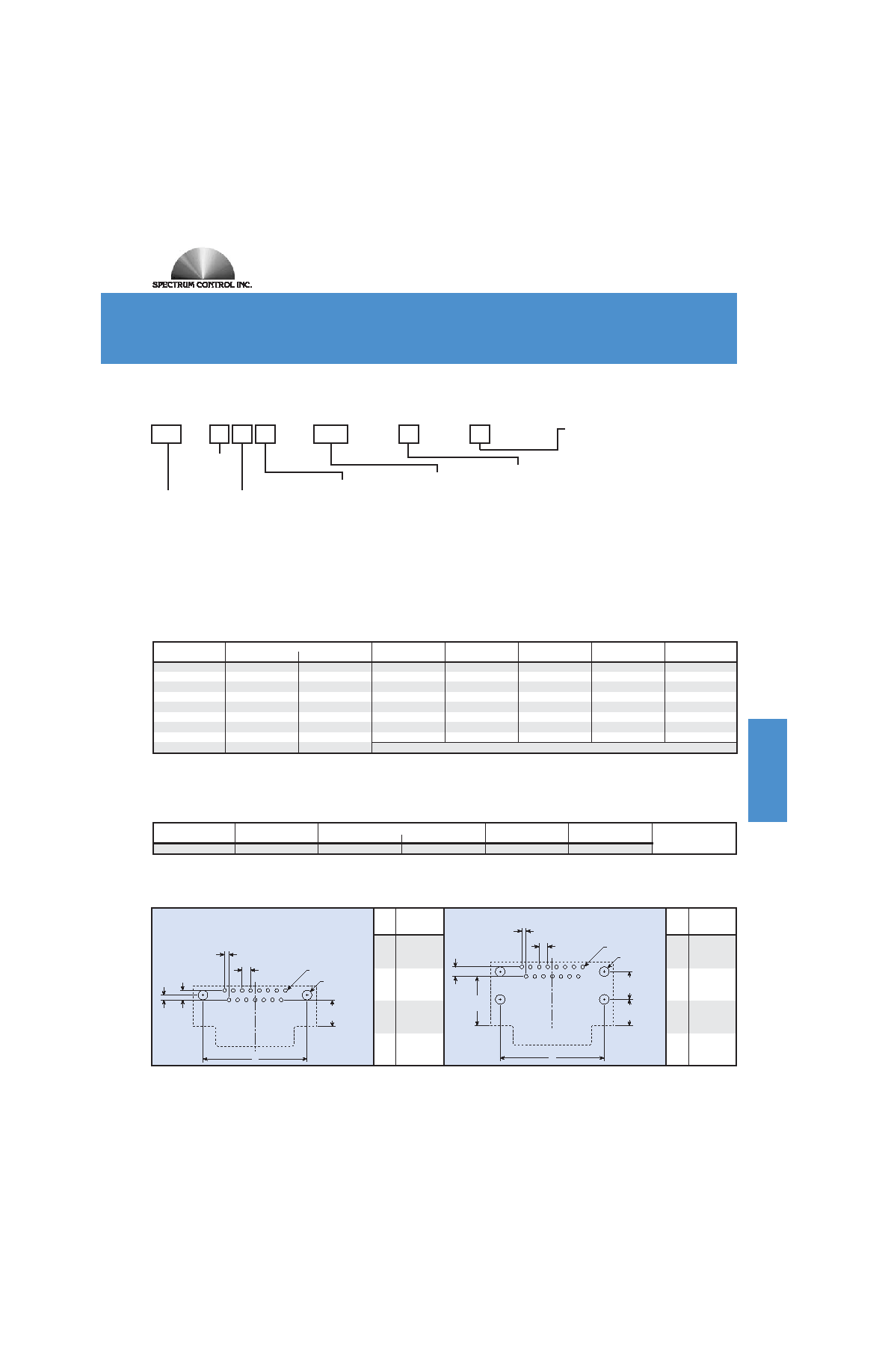
Dimensions in inches
(mm)
.109
(2.77)
.054
(1.385)
.043
(1.09)
.120
(3.05)
.590
(14.99)
.112
(2.84)
.315
(8.00)
B
.315
(8.00)
Board Layouts
.590" Footprint Typical Layout - Top View
Dimensions in inches
(mm)
.109
(2.77)
.054
(1.385)
.043
(1.09)
.120
(3.05)
.112
(2.84)
.056
(1.42)
.318
(8.08)
A
.405
(10.20)
or
.318" and .405" Footprint Typical Layout
- Top View
Shell
B
Size ±.005
(±0.13)
.984
9
(24.99)
1.312
15
(33.32)
1.852
25
(47.04)
2.500
37
(63.50)
Shell
A
Size ±.005
(±0.13)
.984
9
(24.99)
1.312
15
(33.32)
1.852
25
(47.04)
2.500
37
(63.50)
1000
Trigger
Voltage
Typical
*1566 PRINTER 171-241 v2
12/4/06
9:42 AM
Page 9
相關(guān)PDF資料 |
PDF描述 |
|---|---|
| 56-E37-014-3-GBL6 | 37 CONTACT(S), MALE, D SUBMINIATURE CONNECTOR, SOLDER |
| 56-E37-014-3-JS | 37 CONTACT(S), MALE, D SUBMINIATURE CONNECTOR, SOLDER |
| 56-E37-014-3-MIB | 37 CONTACT(S), MALE, D SUBMINIATURE CONNECTOR, SOLDER |
| 56-E37-014-3-TIB | 37 CONTACT(S), MALE, D SUBMINIATURE CONNECTOR, SOLDER |
| 56-E37-014-3-TIF | 37 CONTACT(S), MALE, D SUBMINIATURE CONNECTOR, SOLDER |
相關(guān)代理商/技術(shù)參數(shù) |
參數(shù)描述 |
|---|---|
| 56E6 | 制造商:Cooper Bussmann 功能描述: |
| 56EET | 功能描述:保險絲 THYRISTOR (SPECIAL) RoHS:否 制造商:Littelfuse 產(chǎn)品:Surface Mount Fuses 電流額定值:0.5 A 電壓額定值:600 V 保險絲類型:Fast Acting 保險絲大小/組:Nano 尺寸:12.1 mm L x 4.5 mm W 安裝風格: 端接類型:SMD/SMT 系列:485 |
| 56ELB689 | 制造商:Mitutoyo Corporation 功能描述:LINEAR GAGE FOR HR-320MS |
| 56ES1GY | 制造商:Clipsal Electrical 功能描述:IP66 1 GANG BACK BOX 40MM |
| 56ET | 功能描述:保險絲 56A 690VAC BS88 FUSE RoHS:否 制造商:Littelfuse 產(chǎn)品:Surface Mount Fuses 電流額定值:0.5 A 電壓額定值:600 V 保險絲類型:Fast Acting 保險絲大小/組:Nano 尺寸:12.1 mm L x 4.5 mm W 安裝風格: 端接類型:SMD/SMT 系列:485 |
發(fā)布緊急采購,3分鐘左右您將得到回復(fù)。