- 您現(xiàn)在的位置:買賣IC網(wǎng) > PDF目錄359939 > 48S12.850TC Analog IC PDF資料下載
參數(shù)資料
| 型號(hào): | 48S12.850TC |
| 英文描述: | Analog IC |
| 中文描述: | 模擬IC |
| 文件頁數(shù): | 5/6頁 |
| 文件大小: | 106K |
| 代理商: | 48S12.850TC |
A
30 Watt NT Single Series DC/DC Converters
2401 Stanwell Drive Concord, California 94520 Ph: 925/687-4411 or 800/542-3355 Fax: 925/687-3333 www.calex.com Email: sales@calex.com
5
3/2001
9
!
:;
2:9<9;2
:9;2
#
9;29998
9;
99
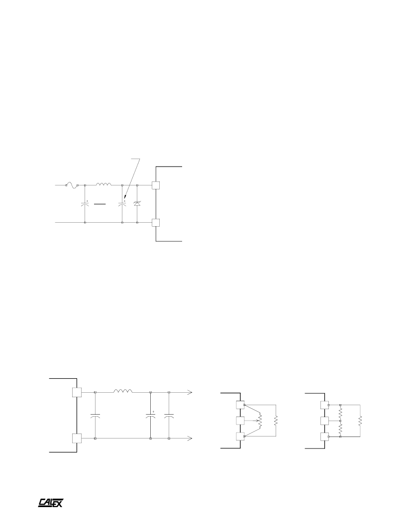
Figure 3.
Low noise output filter circuit
Figure 4.
Output trim methods
The suggested capacitors will work for any line and load
condition, however, they may be oversized for your application.
High ripple current film capacitors may also be used and may
provide longer life or smaller size.
Low Noise Input Filtering Circuit
To reduce the input reflected ripple to less than 100 mA peak-
to-peak the circuit shown in Figure 2 may be used. Use
reasonable caution when selecting an inductor other than the
one specified. Nearly any 105
°
C rated capacitor can be used
for the 10μF / 100V part. To prevent input filter peaking the
ESR should be in the range of 0.5 to 2 ohms. Do not use the
lowest ESR capacitor available for this part. This will render
the filter ineffective.
Figure 2.
Low noise input filter circuit
Input Overvoltage Protection
As shown in figure 1, optional transient overvoltage protection
may be used at the input of the converter. This should be
considered if your application circuit could present a voltage
greater than the NT Series maximum transient voltage listed
on the data sheet. This device could also serve as a reverse
input voltage protector if used with a suitable fuse.
Low Noise Output Filtering Circuit
Extra output filtering is easy with the NT Series due to the high,
constant 200 kHz switching frequency. The optional circuit
shown in figure 3 can reduce the output noise to 15 mV p-p on
a 5 Volt output converter and 40 mV p-p on 12 and 15 Volt
output converters. The inductor should be sized appropriately
for your maximum load current. No extra large capacitance is
required on the output of the converter other than the
components shown and the standard bypassing on your PCB.
Large, low ESR capacitors on the output of the converter can
actually make the output noise worse or cause oscillation.
See the CALEX application note on
“
Understanding Output
Impedance
”
for more information.
Remote ON/OFF Circuit Operation
The remote ON/OFF pin is best applied as follows:
To turn the unit off, the ON/OFF pin should be tied to the -
Input pin. This is best done by an open collector arrangement
or contact closure.
To turn the unit on, let the ON/OFF pin float.
If the remote ON/OFF pin is not used, it may be safely left
floating. There is a 100K internal pull-up resistor inside the
unit to +9 Volts DC.
Other applications of the ON/OFF function can be found in
the application note,
“
Understanding the Remote ON/OFF
Function
”
.
Proper Application Of The Trim Pin
The trim pin is used to adjust the output voltage slightly to
compensate for voltage drops in the system
’
s wiring. Figure
4 shows the proper application of the trim pin. Either a 10K
trimpot or fixed resistors may be used.
Other applications for the TRIM function can be found in the
CALEX application note,
“
Applying the Remote Sense and
Trim Functions on DC/DC Converters.
”
Use one resistor for either trim up or trim down. The values
can range from infinity to zero ohms with zero ohms providing
the most trim.
相關(guān)PDF資料 |
PDF描述 |
|---|---|
| 48S15.2000NT | Dual/Triple Ultra-Low-Voltage SOT23 µP Supervisory Circuits |
| 48S5.2000TC | Dual/Triple Ultra-Low-Voltage SOT23 µP Supervisory Circuits |
| 48S5.5000NT | Analog IC |
| 48S15.700TC | Analog IC |
| 48S15.10000TC | SMPS Controller |
相關(guān)代理商/技術(shù)參數(shù) |
參數(shù)描述 |
|---|---|
| 48S5.3000BR | 制造商:CALEX 功能描述: |
| 48SC-003A-M2 | 制造商:JVC Worldwide 功能描述:SCREEN ASSY |
| 48SC004 | 功能描述:塑料硬件 SPEAKER CLIP RoHS:否 制造商:3M Electronic Specialty 類型:Cylindrical Bumpers |
| 48SD1616 | 制造商:MAXWELL 制造商全稱:Maxwell Technologies 功能描述:256 Mb SDRAM 4-Meg X 16-Bit X 4-Banks |
| 48SD1616RPFE | 制造商:MAXWELL 制造商全稱:Maxwell Technologies 功能描述:256 Mb SDRAM 4-Meg X 16-Bit X 4-Banks |
發(fā)布緊急采購,3分鐘左右您將得到回復(fù)。