- 您現(xiàn)在的位置:買賣IC網(wǎng) > PDF目錄30639 > 4416H-R2R-503 (Bourns Inc.) R/2R Ladder Networks PDF資料下載
參數(shù)資料
| 型號: | 4416H-R2R-503 |
| 廠商: | Bourns Inc. |
| 英文描述: | R/2R Ladder Networks |
| 中文描述: | R/2R階梯網(wǎng)絡(luò) |
| 文件頁數(shù): | 1/1頁 |
| 文件大小: | 70K |
| 代理商: | 4416H-R2R-503 |

Specifications are subject to change without notice.
331
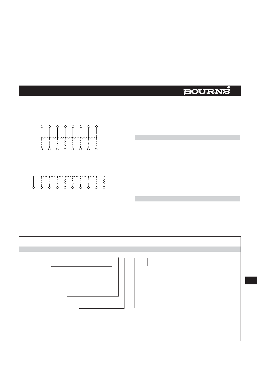
R/2R Ladder Networks are available in both DIP and SIP
(Molded or Conformal) configurations.
16
1
9
8
2R
R
2R
15
2
2R
R
14
3
2R
R
13
4
2R
R
12
5
2R
R
11
6
2R
R
10
7
2R
R
2R
OUT
RT
16-PIN
8-BIT
DIP
PIN
BIT
18
23
4
5
6
7
MSB
LSB
2
2R
R
3
2R
R
4
2R
R
5
2R
R
6
2R
R
7
2R
R
8
2R
R
9
2R
1
BIT OUT
18
23
4
5
6
7
MSB
LSB
PIN
10
2R
RT
10-PIN
8-BIT
SIP
The R/2R Ladder Network is commonly used for Digital to
Analog (D/A) conversions and Analog to Digital (A/D) conversion
by successive approximations. The bits of the ladder are the
points at which input signals are presented to the ladder and
the output terminal (OUT) is the point at which the output is
taken from the R/2R ladder. This terminal (OUT) is commonly
used to drive an operational amplifier. RT (the terminating resis-
tor) is always connected to ground.
Standard R/2R Ladder Networks have a resistance tolerance of
±2.0% (±1.0% available on all but low profile SIPs).
Standard R/2R Ladder Networks
Availability is as follows:
DIP/SMD
SIP-CONFORMAL
SIP MOLDED
14 Pin - 7 Bit
6 Pin - 4 Bit
16 Pin - 8 Bit
7 Pin - 5 Bit
8 Pin - 6 Bit
10 Pin - 8 Bit
9 Pin - 7 Bit
10 Pin - 8 Bit
11 Pin - 9 Bit
12 Pin -10 Bit
14 Pin -12 Bit
Resistor Power Ratings @ 70 C
Low Profile SIP & DIP ....................................................
.125W
Medium Profile SIP ........................................................
.170W
High Profile SIP ..............................................................
.200W
How To Order R/2R Ladder Networks
41 16 R - R2R - 503
Model
Resistance/Capacitance Code
(41 = Molded DIP)
(For value of R). 2R is double this value.
(43 = Molded SIP)
First 2 digits are significant.
(44 = Wide Body SMD)
Third digit represents the number
(46 = Conformal SIP)
of zeros to follow.
(48 = SMD)
Number of Pins
Physical Configuration
Electrical Configuration
(R = Low Profile - Molded)
R2R = R/2R Ladder Network
(X = Low Profile - Conformal)
(M = Medium Profile)
(H = High Profile)
(P = Medium Body SOIC)
R/2R Ladder Networks
相關(guān)PDF資料 |
PDF描述 |
|---|---|
| 4416M-R2R-503 | R/2R Ladder Networks |
| 4416P-R2R-503 | R/2R Ladder Networks |
| 4416R-R2R-503 | R/2R Ladder Networks |
| 4416T-1-2222BAAL | Thin Film Wide Body Gull Wing |
| 4416T-1-2222BABL | Thin Film Wide Body Gull Wing |
相關(guān)代理商/技術(shù)參數(shù) |
參數(shù)描述 |
|---|---|
| 4416J001 | 制造商:未知廠家 制造商全稱:未知廠家 功能描述:Interface IC |
| 4416J002 | 制造商:未知廠家 制造商全稱:未知廠家 功能描述:Interface IC |
| 4416J003 | 制造商:未知廠家 制造商全稱:未知廠家 功能描述:Interface IC |
| 4416J004 | 制造商:未知廠家 制造商全稱:未知廠家 功能描述:Interface IC |
| 4416M | 制造商:ebm-papst Inc 功能描述:DC Fan 119x38mm |
發(fā)布緊急采購,3分鐘左右您將得到回復(fù)。