- 您現(xiàn)在的位置:買賣IC網(wǎng) > PDF目錄358625 > 322CNQ030 (International Rectifier) 300 Amp Schottky Rectifier(300 A 肖特基整流器) PDF資料下載
參數(shù)資料
| 型號: | 322CNQ030 |
| 廠商: | International Rectifier |
| 英文描述: | 300 Amp Schottky Rectifier(300 A 肖特基整流器) |
| 中文描述: | 300安培肖特基整流器(300甲肖特基整流器) |
| 文件頁數(shù): | 2/2頁 |
| 文件大?。?/td> | 24K |
| 代理商: | 322CNQ030 |
322CNQ030
Preliminary Data Sheet PD-2.550
01/98
2
www.irf.com
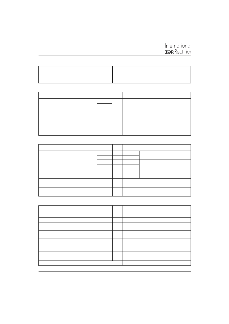
I
F(AV)
Max. Average Forward Current
(Per Leg)
I
FSM
Surge Current (Per Leg)
300
150
10,000
1500
A
A
50% duty cycle @ T
C
= 87 °C, rectangular wave form
Max. Peak One Cycle Non-Repetitive
5μs Sine or 3μs Rect. pulse
10ms Sine or 6ms Rect. pulse
E
AS
Non-Repetitive Avalanche Energy
(Per Leg)
Repetitive Avalanche Current
(Per Leg)
270
mJ
T
J
= 25 °C, I
AS
= 1 Amps, L = 30 mH
I
AR
60
A
Current decaying linearly to zero in 1 μsec
Frequency limited by T
J
max. V
A
= 1.5 x V
R
typical
T
J
T
stg
R
thJC
Max. Thermal Resistance Junction
to Case (Per Leg)
R
thJC
Max. Thermal Resistance Junction
to Case (Per Package)
R
thCS
Typical Thermal Resistance, Case
to Heatsink
wt
Approximate Weight
T
Mounting Torque
Max. Junction Temperature Range
Max. Storage Temperature Range
-55 o 150
-55 o 150
0.50
°C
°C
°C/W DC operation
0.25
°C/W DC operation
0.10
°C/W Mounting surface , smooth and greased
58 (2.0)
40 (35)
58 (50)
g (oz.)
Min.
Max.
Case Style
TO - 249AA
JEDEC
Thermal-Mechanical Specifications
Kg-cm
(Ibf-in)
V
FM
Max. Forward Voltage Drop
(Per Leg)
0.56
0.70
0.49
0.68
10
650
5500
8.0
10,000
V
V
V
V
@ 150A
@ 300A
@ 150A
@ 300A
T
J
= 25 °C
T
J
= 125 °C
V
R
= 5V
DC
, (test signal range 100Khz to 1Mhz) 25°C
Measured from terminal hole to terminal hole
I
RM
Max. Reverse Leakage Current
(Per Leg)
Max. Junction Capacitance (Per Leg)
Typical Series Inductance (Per Leg)
dv/dt Max. Voltage Rate of Change
(Rated V
R
)
mA
mA
pF
nH
V/ μs
C
T
L
S
T
J
= 25 °C
T
J
= 125 °C
Electrical Specifications
(1) Pulse Width < 300μs, Duty Cycle <2%
V
R
= rated V
R
Absolute Maximum Ratings
Following any rated
load condition and with
rated V
RRM
applied
Parameters
322CNQ Units
Conditions
A
Part number
V
R
V
RWM
Max.
Working Peak Reverse Voltage (V)
322CNQ030
Max.
DC Reverse Voltage (V)
Parameters
322CNQ Units
Conditions
Parameters
322CNQ Units
Conditions
Voltage Ratings
30
相關(guān)PDF資料 |
PDF描述 |
|---|---|
| 3239-00 | 2.2 GHz Integer-N PLL for Low Phase Noise Applications |
| 323GT | 5.0mm Round Type LED Lamps |
| 3245A-MSOP8 | Constant Current Forward/Reverse Driver IC for Digital Cameras |
| 3250 | Square Trimming Potentiometer |
| 3250 | MONOLITHIC DUAL NPN TRANSISTORS |
相關(guān)代理商/技術(shù)參數(shù) |
參數(shù)描述 |
|---|---|
| 322CNQ030_03 | 制造商:IRF 制造商全稱:International Rectifier 功能描述:SCHOTTKY RECTIFIER |
| 322DC-6 | 功能描述:FILTRETE DUST REDUCTION FILTERS 制造商:3m 系列:* 零件狀態(tài):在售 標準包裝:6 |
| 322F157K015AS | 制造商: 功能描述: 制造商:undefined 功能描述: |
| 322-FBG/03 | 制造商:Weco Elec. Conn. 功能描述:Conn Terminal Block 3 POS 10mm Solder ST Thru-Hole 20A |
| 322-FBG/04 | 制造商:Weco Elec. Conn. 功能描述:Conn Terminal Block 4 POS 10mm Solder ST Thru-Hole 20A |
發(fā)布緊急采購,3分鐘左右您將得到回復(fù)。