- 您現(xiàn)在的位置:買賣IC網(wǎng) > PDF目錄371445 > 2MBI300NB-060-01 (FUJI ELECTRIC CO LTD) 600V / 300A 2 in one-package PDF資料下載
參數(shù)資料
| 型號: | 2MBI300NB-060-01 |
| 廠商: | FUJI ELECTRIC CO LTD |
| 元件分類: | IGBT 晶體管 |
| 英文描述: | 600V / 300A 2 in one-package |
| 中文描述: | 300 A, 600 V, N-CHANNEL IGBT |
| 封裝: | MODULE-7 |
| 文件頁數(shù): | 1/4頁 |
| 文件大小: | 181K |
| 代理商: | 2MBI300NB-060-01 |
2MBI300NB-060-01
600V / 300A 2 in one-package
IGBT Module
Features
· VCE(sat) classified for easy parallel connection
· High speed switching
· Voltage drive
· Low inductance module structure
Applications
· Inverter for Motor drive
· AC and DC Servo drive amplifier
· Uninterruptible power supply
· Industrial machines, such as Welding machines
Maximum ratings and characteristics
Absolute maximum ratings (at Tc=25°C unless otherwise specified)
Item
Symbol
Collector-Emitter voltage V
CES
Gate-Emitter voltage V
GES
Collector Continuous I
C
current 1ms I
C
pulse
-I
C
1ms -I
C
pulse
Max. power dissipation P
C
Operating temperature T
j
Storage temperature T
stg
Isolation voltage V
is
Screw torque Mounting *
1
Terminals *
2
Rating
600
±20
300
600
300
600
1100
+150
-40 to +125
AC 2500 (1min.)
3.5
4.5
Unit
V
V
A
A
A
A
W
°C
°C
V
N·m
N·m
Item Symbol Characteristics Condtions Unit
Min. Typ. Max.
Zero gate voltage collector current
Gate-Emitter leakage current
Gate-Emitter threshold voltage
Collector-Emitter saturation voltage
Input capacitance
Output capacitance
Reverse transfer capacitance
Turn-on time
t
on
t
r
t
off
t
f
V
F
t
rr
– – 0.3
Turn-off time
Diode forward on voltage
Reverse recovery time
I
CES
I
GES
V
GE(th)
V
CE(sat)
C
ies
C
oes
C
res
– – 2.0
– – 30
4.5 – 7.5
– – 2.8
– 19800 –
– 4400 –
– 2000 –
– 0.6 1.2
– 0.2 0.6
– 0.6 1.0
– 0.2 0.35
– – 3.0
V
GE
=0V, V
CE
=600V
V
CE
=0V, V
GE
=±20V
V
CE
=20V, I
C
=300mA
V
GE
=15V, I
C
=300A
V
GE
=0V
V
CE
=10V
f=1MHz
V
CC
=300V
I
C
=300A
V
GE
=±15V
R
G
=6.8ohm
I
F
=300A, V
GE
=0V
I
F
=300A
mA
μA
V
V
pF
μs
V
μs
Electrical characteristics (at Tj=25°C unless otherwise specified)
Thermal resistance characteristics
Item Symbol Characteristics Condtions Unit
Min. Typ. Max.
Rth(j-c)
Thermal resistance Rth(j-c)
Rth(c-f)*
– 0.025 –
* :
This is the value which is defined mounting on the additional cooling fin with thermal compound
– – 0.11
– – 0.15
IGBT
Diode
the base to cooling fin
°C/W
°C/W
°C/W
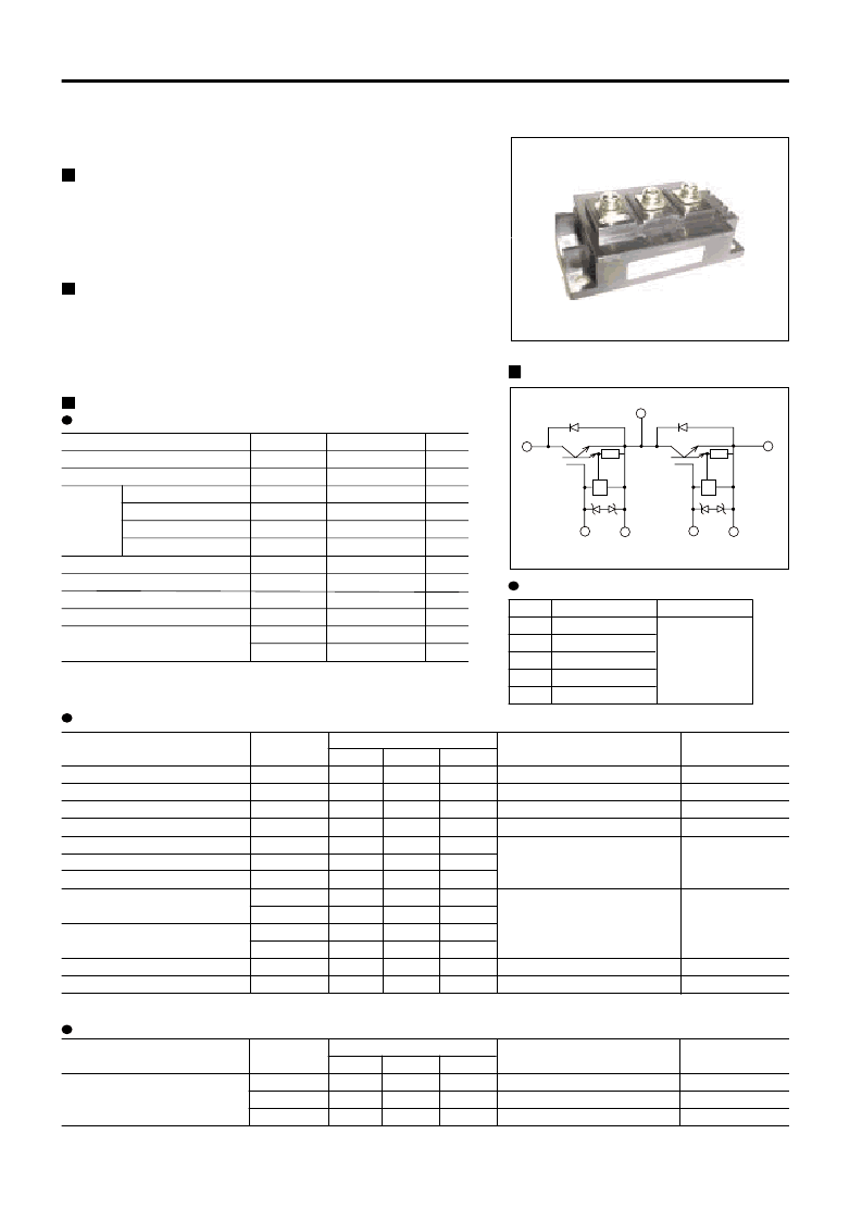
Equivalent Circuit Schematic
¤ Current control circuit
G1 E1 G2 E2
C1
E2
C2E1
¤
¤
*
1 :
Recommendable value : 2.5 to 3.5 N·m (M5) or (M6)
*
2 :
Recommendable value : 3.5 to 4.5 N·m (M6)
VCE(sat) classification
Rank Lenge Conditions
F 1.85 to 2.10V
A 2.00 to 2.25V Ic = 300A
B 2.15 to 2.40V V
GE
= 15V
C 2.30 to 2.60V Tj = 25°C
D 2.50 to 2.80V
相關(guān)PDF資料 |
PDF描述 |
|---|---|
| 2MBI300NT-120-02 | IGBT module |
| 2MBI300TA-060 | IGBT Module |
| 2MBI300U4D-120 | IGBT MODULE |
| 2MBI300U4E-120 | IGBT MODULE |
| 2MBI300U4H-120 | IGBT MODULE |
相關(guān)代理商/技術(shù)參數(shù) |
參數(shù)描述 |
|---|---|
| 2MBI300NT-120-02 | 制造商:FUJI 制造商全稱:Fuji Electric 功能描述:IGBT module |
| 2MBI300P-140 | 制造商:FUJI 制造商全稱:Fuji Electric 功能描述:1400V/300A 2-Pack IGBT |
| 2MBI300P-140_04 | 制造商:FUJI 制造商全稱:Fuji Electric 功能描述:IGBT Module |
| 2MBI300S-120 | 制造商:未知廠家 制造商全稱:未知廠家 功能描述:DUAL IGBT |
| 2MBI300TA-060 | 制造商:FUJI 制造商全稱:Fuji Electric 功能描述:IGBT Module |
發(fā)布緊急采購,3分鐘左右您將得到回復(fù)。