- 您現(xiàn)在的位置:買賣IC網(wǎng) > PDF目錄371376 > 22RIA120M (International Rectifier) MEDIUM POWER THYRISTORS PDF資料下載
參數(shù)資料
| 型號: | 22RIA120M |
| 廠商: | International Rectifier |
| 英文描述: | MEDIUM POWER THYRISTORS |
| 中文描述: | 中功率晶閘管 |
| 文件頁數(shù): | 3/9頁 |
| 文件大?。?/td> | 225K |
| 代理商: | 22RIA120M |
22RIA Series
Bulletin I2403 rev. A 07/00
3
www.irf.com
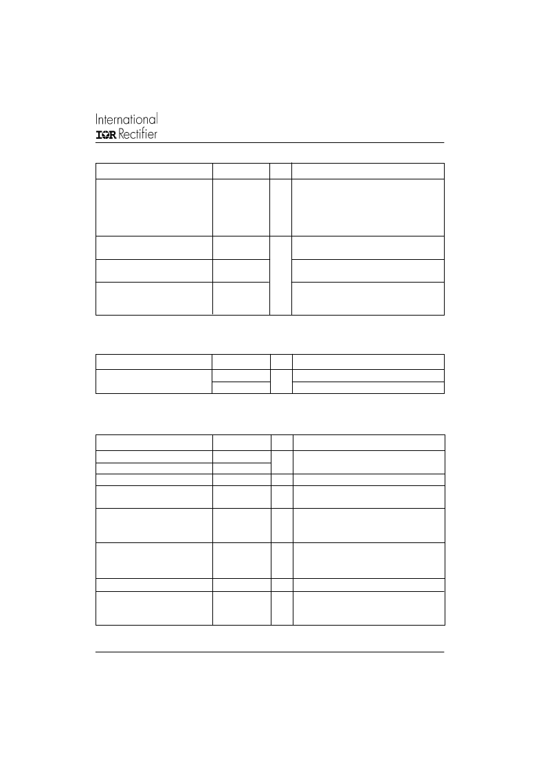
dv/dt
Max. critical rate of rise of
100
T
J
= T
J
max. linear to 100% rated V
DRM
off-state voltage
300 (*)
T
J
= T
J
max. linear to 67% rated V
DRM
V/μs
Parameter
22RIA
Units
Conditions
Blocking
P
GM
P
G(AV)
Maximum average gate power
I
GM
Max. peak positive gate current
-V
GM
Maximum peak negative
gate voltage
Maximum peak gate power
8.0
T
J
= T
J
max.
2.0
1.5
A
T
J
= T
J
max.
T
J
= T
J
max.
10
V
I
GT
DC gate current required
90
T
J
= - 65°C
T
J
= 25°C
to trigger
60
mA
35
T
J
= 125°C
T
J
= - 65°C
V
GT
DC gate voltage required
3.0
to trigger
2.0
V
T
J
= 25°C
T
J
= 125°C
T
J
= T
J
max., V
DRM
= rated value
1.0
V
I
GD
DC gate current not to trigger
2.0
mA
V
GD
DC gate voltage not to trigger
0.2
V
T
J
= T
J
max.
V
DRM
= rated value
W
Max. required gate trigger current/
voltage are the lowest value which
will trigger all units 6V anode-to-
cathode applied
Max. gate current/ voltage not to
trigger is the max. value which
will not trigger any unit with rated
V
DRM
anode-to-cathode applied
Parameter
22RIA
Units
Conditions
Triggering
di/dt
Max. rate of rise of turned-on
T
J
= T
J
max., V
DM
= rated V
DRM
Gate pulse = 20V, 15
, t
p
= 6μs, t
r
= 0.1μs max.
I
TM
= (2x rated di/dt) A
current
V
DRM
≤
600V
V
DRM
≤
800V
V
DRM
≤
1000V
V
DRM
≤
1600V
200
A/μs
180
160
150
t
gt
Typical turn-on time
0.9
T
J
= 25°C,
at = rated V
DRM
/V
RRM
, T
J
= 125°C
T
J
= T
J
max.,
I
TM
= I
T(AV)
, t
p
> 200μs, di/dt = -10A/μs
T
J
= T
J
max., I
TM
= I
T(AV)
, t
p
> 200μs,
V
R
= 100V,
di/dt = -10A/μs, dv/dt = 20V/μs linear to
t
rr
Typical reverse recovery time
4
μs
t
q
Typical turn-off time
110
67% V
DRM
, gate bias 0V-100W
Parameter
22RIA
Units
Conditions
Switching
(**) Available with: dv/dt = 1000V/μs, to complete code add S90 i.e. 22RIA160S90.
(*) t
q
= 10μsup to 600V, t
q
= 30μs up to 1600V available on special request.
相關(guān)PDF資料 |
PDF描述 |
|---|---|
| 22RIA120MS90 | MEDIUM POWER THYRISTORS |
| 22RIA120S90 | MEDIUM POWER THYRISTORS |
| 22RIA140 | MEDIUM POWER THYRISTORS |
| 22RIA140M | MEDIUM POWER THYRISTORS |
| 22RIA140MS90 | MEDIUM POWER THYRISTORS |
相關(guān)代理商/技術(shù)參數(shù) |
參數(shù)描述 |
|---|---|
| 22RIA120MS90 | 制造商:VISHAY 制造商全稱:Vishay Siliconix 功能描述:Medium Power Thyristors (Stud Version), 22 A |
| 22RIA120PBF | 制造商:Vishay 功能描述:Bulk 制造商:International Rectifier 功能描述:THYRISTOR 22A 1200V TO-48 |
| 22RIA120S90 | 制造商:IRF 制造商全稱:International Rectifier 功能描述:MEDIUM POWER THYRISTORS |
| 22RIA140 | 制造商:IRF 制造商全稱:International Rectifier 功能描述:MEDIUM POWER THYRISTORS |
| 22RIA140M | 制造商:IRF 制造商全稱:International Rectifier 功能描述:MEDIUM POWER THYRISTORS |
發(fā)布緊急采購,3分鐘左右您將得到回復(fù)。