- 您現(xiàn)在的位置:買賣IC網(wǎng) > PDF目錄63055 > 167 SPECIALTY ANALOG CIRCUIT, DMA21 PDF資料下載
參數(shù)資料
| 型號(hào): | 167 |
| 元件分類: | 模擬信號(hào)調(diào)理 |
| 英文描述: | SPECIALTY ANALOG CIRCUIT, DMA21 |
| 封裝: | 2 X 2 INCH, 0.600 INCH HEIGHT, MODULE-31/21 |
| 文件頁數(shù): | 5/5頁 |
| 文件大?。?/td> | 269K |
| 代理商: | 167 |

A
5
CALEX
FaxFACTS:
315
1997
Models 166 and 167 Bridgesensors
http://www.calex.com
2401 Stanwell Drive
Concord, CA 94520-4841
(510) 687-4411 Fax (510) 687-3333
Maximum current through the LED portion of the optical
coupler is 13 mA, which results in a minimum phototransistor
current of 2 mA. If the phototransistor is used to switch 5
Volts, then its collector resistor should be limited to
approximately 1 kohm.
The Model 167 output circuit provides for sinking 50 mA,
sourcing 2 mA into 5k or for using a separate collector supply.
For example, if TTL digital circuitry is to be driven by the Model
167, the external jumper between pin 3 and 5 can be left out.
Then a separate 5 Volt source can be connected to the
collector of Q1 through pin 5 and a load resistor. Figure 5
shows a typical application.
Amplifier Frequency Response
The amplifier bandwidth is 10 kHz at a gain of 100. The rolloff
response curve is 20 dB per decade so the 3 dB down
frequency can be predicted by knowing the gain setting. For
example, at a gain setting of 1000, bw = 1 kHz, and at 10, bw
= 100 kHz. It is sometimes desirable to intentionally limit the
amplifier frequency response in order to minimize the effect
of high frequency noise. The input stage of the V/F converter
is an active integrator with a time constant of about 0.5 ms
(Model 166), it therefore does not require a bandwidth limit.
However, if the amplifier output is also to be monitored by an
external device such as a scope or recorder then the user
may wish to use additional filtering. This can be done by
connecting a simple RC network or an active filter between
the monitoring device and the amplifier output. Capacitors
should not be connected directly across the amplifier output
since this may cause instability.
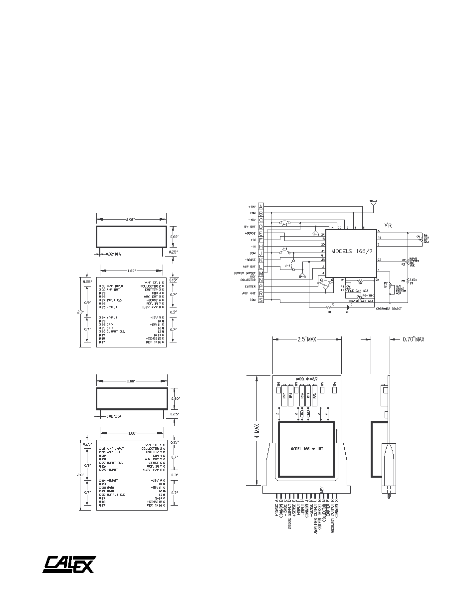
Mechanical Specifications
FIGURE 6. Outline Dimensions
MODEL 166
Shaded pins not installed. Shown for position only.
MODEL 167
Shaded pins not installed. Shown for position only.
FIGURE 8. MK 166/7 Mounting Kit Dimensions
FIGURE 7. MK 166/7 Mounting Kit Schematic
相關(guān)PDF資料 |
PDF描述 |
|---|---|
| 1672250100 | Fuse |
| 1672300100 | Fuse |
| 167293-1 | 15 WAY PLUG BODY |
| 167295-1 | 37 WAY PLUG BODY |
| 1673921 | SILICONE ELASTOMER SYLGARD 1.1KG |
相關(guān)代理商/技術(shù)參數(shù) |
參數(shù)描述 |
|---|---|
| 167.125.150 | 制造商:Igus 功能描述:ENERGY TUBE CHAIN 150MM |
| 167/6 | 制造商:Greenlee Textron Inc 功能描述:WIRE FERL INSUL |
| 167/8 | 制造商:Greenlee Textron Inc 功能描述:WIRE FERL INSUL |
| 167/HL | 制造商:Greenlee Textron Inc 功能描述:WIRE FERL INSUL |
| 1670 | 功能描述:臺(tái)式電源 PS 0-30 12 & 5VDC RoHS:否 制造商:B&K Precision 類型:DC Electronic Loads (Programmable) 輸入電壓:110 VAC, 220 VAC Selectable 輸出端數(shù)量: 輸出電壓(通道 1):0.1 V to 120 V 輸出電流(通道 1):30 A 輸出電壓(通道 2): 輸出電流(通道 2): 輸出電壓(通道 3): 輸出電流(通道 3): 顯示器類型:VFD |
發(fā)布緊急采購,3分鐘左右您將得到回復(fù)。