- 您現(xiàn)在的位置:買賣IC網(wǎng) > PDF目錄106295 > 15IWR1-12-N 1-OUTPUT 1 W DC-DC REG PWR SUPPLY MODULE PDF資料下載
參數(shù)資料
| 型號: | 15IWR1-12-N |
| 元件分類: | 電源模塊 |
| 英文描述: | 1-OUTPUT 1 W DC-DC REG PWR SUPPLY MODULE |
| 封裝: | PLASTIC, DIP-24 |
| 文件頁數(shù): | 5/8頁 |
| 文件大小: | 183K |
| 代理商: | 15IWR1-12-N |

1 Watt-Family
DC-DC Converters <40 W
Rugged Environment
6 - 6
Edition 2/96 - Melcher AG
MELCHER
The Power Partners.
6.1
Installation Instructions
Isolation Tests
Input to output isolation voltage tests are performed as factory tests (100 %) and should not be repeated in the field.
Melcher will not honour any guarantee/warranty claims resulting from high voltage field tests.
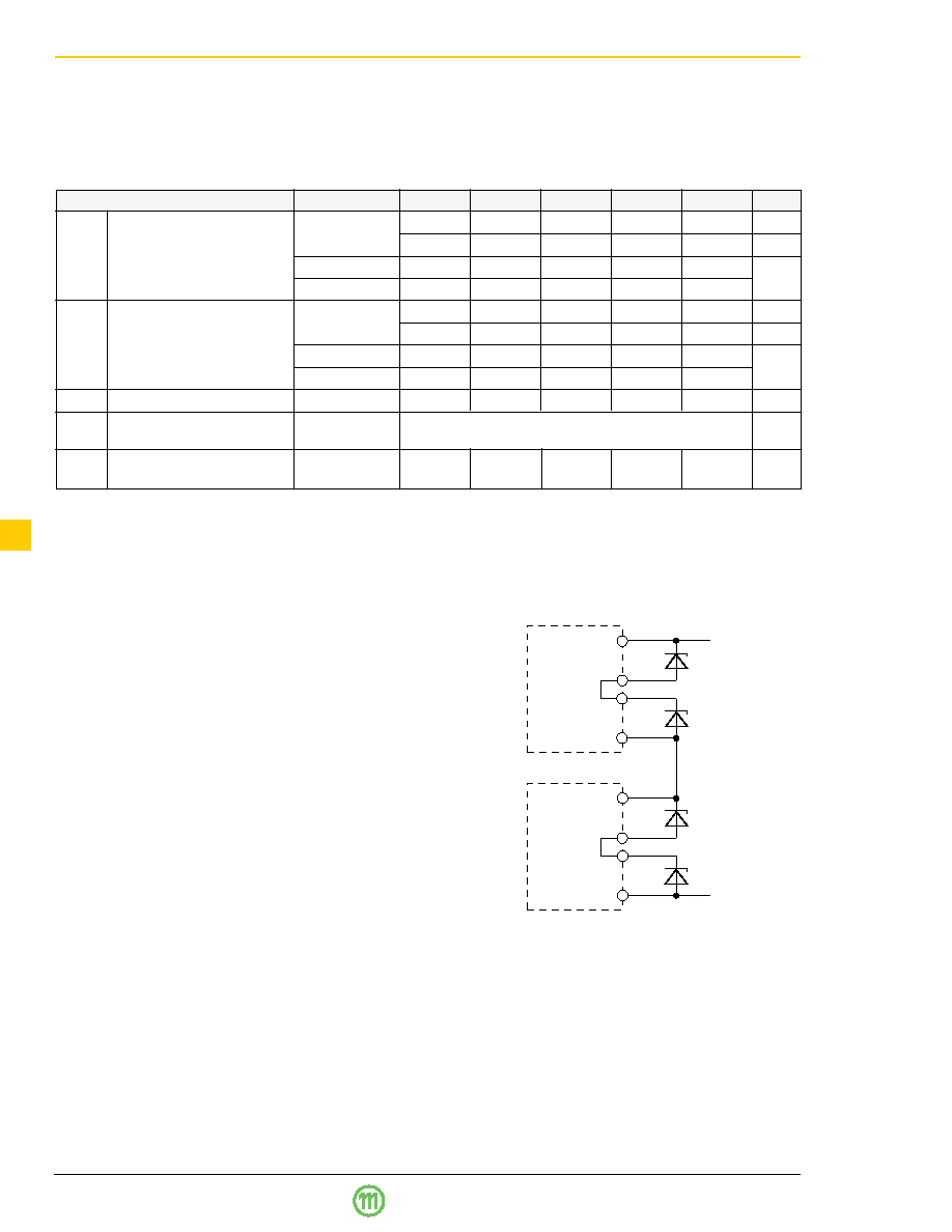
Table 8: Isolation test voltage, coupling capacitance, insulation resistance, clearance and creepage distances
Characteristics
Conditions
ICR
IWR 1
IXR
IYR
IZR
Unit
Uis io
Isolation test voltage
AC: 50 Hz,
500
1060
2500
3750
5000
Vrms
Input to output
1 minute
1400
3000
7070
10600
14100
Vpp
DC: 1 second 2
700
1500
3530
5300
7070
V
DC: 1 second 3
800
1700
4000
6000
8000
Uis oo
Isolation test voltage
AC: 50 Hz,
500
1060
Vrms
output to output 4
1 minute
1400
3000
Vpp
DC: 1 second 2
700
1500
V
DC: 1 second 3
800
1700
Cio
Coupling capacitance
typ
20
10
pF
Ris
Insulation resistance
at 100 V DC
≥1000
M
after 1 minute
dio
Clearance and creepage
≥0.6
≥1
≥3 5
mm
distances input to output
1 According to EN 41003 (1993)
2 For production test purposes in accordance with IEC 950/EN 60950
3 Factory test procedure
4 Groups 03, 05, 08 and 13
5 In combination with the high isolation strength of the potting compound, isolation test voltages mentioned are guaranteed.
Connection in Series
If the outputs of one or more units are connected in series
each individual output should be protected by a zener diode
or preferably by a suppressor diode to avoid overvoltages
or reverse polarity at the individual outputs, e.g.:
– 1N5908 to protect 5 V outputs
– BZW04-11 to protect 12 V outputs
– BZW04-14 to protect 15 V outputs
(or equivalent types)
Such destructive voltages may occur at switch-on cycle of
the converters, if the output voltages do not rise at the same
time. The "slower" output(s) could be supplied and, as a
result, destroyed by the "faster" output(s) via the load. The
maximum output current is limited by the lowest current
limitation.
Connection in Parallel
Connection of the outputs of one or more units in parallel is
not permitted. The load distribution and the ripple values
could not be controlled.
Cleaning
Two CFC free cleaning solvents have been tested and can
be recommended:
– Prozone from BP
– Zestron from Dr. O. K. Wack Chemie GmbH (Germany)
Unit 1
Unit 2
+
Uo
–
Uo
+Vo
Go
–Vo
+Vo
Go
–Vo
Submersion of the units in water for rinsing is permitted.
Drying should be done in the air.
Fig. 1
Outputs connected in series
相關(guān)PDF資料 |
PDF描述 |
|---|---|
| 15IWR1-2X1515-T | 4-OUTPUT 1 W DC-DC REG PWR SUPPLY MODULE |
| 153-006006K | 1-OUTPUT 6 W DC-DC REG PWR SUPPLY MODULE |
| 15IWR1-05-05-S | 2-OUTPUT 1 W DC-DC REG PWR SUPPLY MODULE |
| 15IWR1-15-15-T | 2-OUTPUT 1 W DC-DC REG PWR SUPPLY MODULE |
| 113F3 | 1-OUTPUT DC-DC REG PWR SUPPLY MODULE |
相關(guān)代理商/技術(shù)參數(shù) |
參數(shù)描述 |
|---|---|
| 15-IX0F12.5-32.768 | 制造商:ILSI 制造商全稱:ILSI America LLC 功能描述:2 Lead Metal Package Crystal, 3 mm x 8 mm, 2 mm x 6 mm, 1 mm x 5 mm |
| 15-IX1F12.5-32.768 | 制造商:ILSI 制造商全稱:ILSI America LLC 功能描述:2 Lead Metal Package Crystal, 3 mm x 8 mm, 2 mm x 6 mm, 1 mm x 5 mm |
| 15-IX2F12.5-32.768 | 制造商:ILSI 制造商全稱:ILSI America LLC 功能描述:2 Lead Metal Package Crystal, 3 mm x 8 mm, 2 mm x 6 mm, 1 mm x 5 mm |
| 15-IX3F12.5-32.768 | 制造商:ILSI 制造商全稱:ILSI America LLC 功能描述:2 Lead Metal Package Crystal, 3 mm x 8 mm, 2 mm x 6 mm, 1 mm x 5 mm |
| 15-IX5F12.5-32.768 | 制造商:ILSI 制造商全稱:ILSI America LLC 功能描述:2 Lead Metal Package Crystal, 3 mm x 8 mm, 2 mm x 6 mm, 1 mm x 5 mm |
發(fā)布緊急采購,3分鐘左右您將得到回復(fù)。