- 您現(xiàn)在的位置:買賣IC網(wǎng) > PDF目錄106297 > 110IMY15-05-8RGIL 1-OUTPUT 17.8 W DC-DC REG PWR SUPPLY MODULE PDF資料下載
參數(shù)資料
| 型號: | 110IMY15-05-8RGIL |
| 元件分類: | 電源模塊 |
| 英文描述: | 1-OUTPUT 17.8 W DC-DC REG PWR SUPPLY MODULE |
| 文件頁數(shù): | 4/20頁 |
| 文件大小: | 319K |
| 代理商: | 110IMY15-05-8RGIL |

Board Mountable
DC-DC Converters
IMX/IMY 15 Series
Edition 7/5.2000
12/20
Auxiliary Functions
Shut Down Function
The outputs of the converters may be enabled or disabled
by means of a logic signal (TTL, CMOS, etc.) applied to the
shut down pin. If the shut down function is not required then
it should be left open-circuit.
Converter operating:
2.0...20 V
Converter shut down:
–10...0.7 V
Adjustable Output Voltage
– R input for single output units using synchronous rectifi-
cation (G)
– R input for single output units and -0503- types; optional
for double output units
– Trim input for double output units
As a standard feature, the single and double output units of-
fer adjustable output voltage(s) by using the control input R
or Trim. If the control input is left open-circuit the output volt-
age is set to
Uo nom. For output voltages Uo > Uo nom, the
minimum input voltage
Ui min (see: Electrical Input Data) in-
creases proportionally to
Uo/Uo nom.
Single output units using synchronous rectification (G):
The R input is referenced to the secondary side of the con-
verter. Adjustment of the output voltage is possible by
means of an external resistor connected between the R pin
and either Vo+ or Vo–.
Note: For the units with synchronous rectification
Uo ad-
justment is different from the standard single output units
and -0503- types.
Double output units with Trim input:
The Trim input is referenced to the primary side. The figure
below shows the circuit topology. Adjustment of the output
voltage is possible by means of either an external resistor
Rext in the range of 100...105% of Uo nom or an external volt-
age source in the range of 75...105% of
Uo nom.
Trim
Vo1+
Vo2–
+
U
ext
–
Vi+
Vi–
R
ext
Vo1–
Vo2+
06089
Control
circuit
Uref 2.5 V
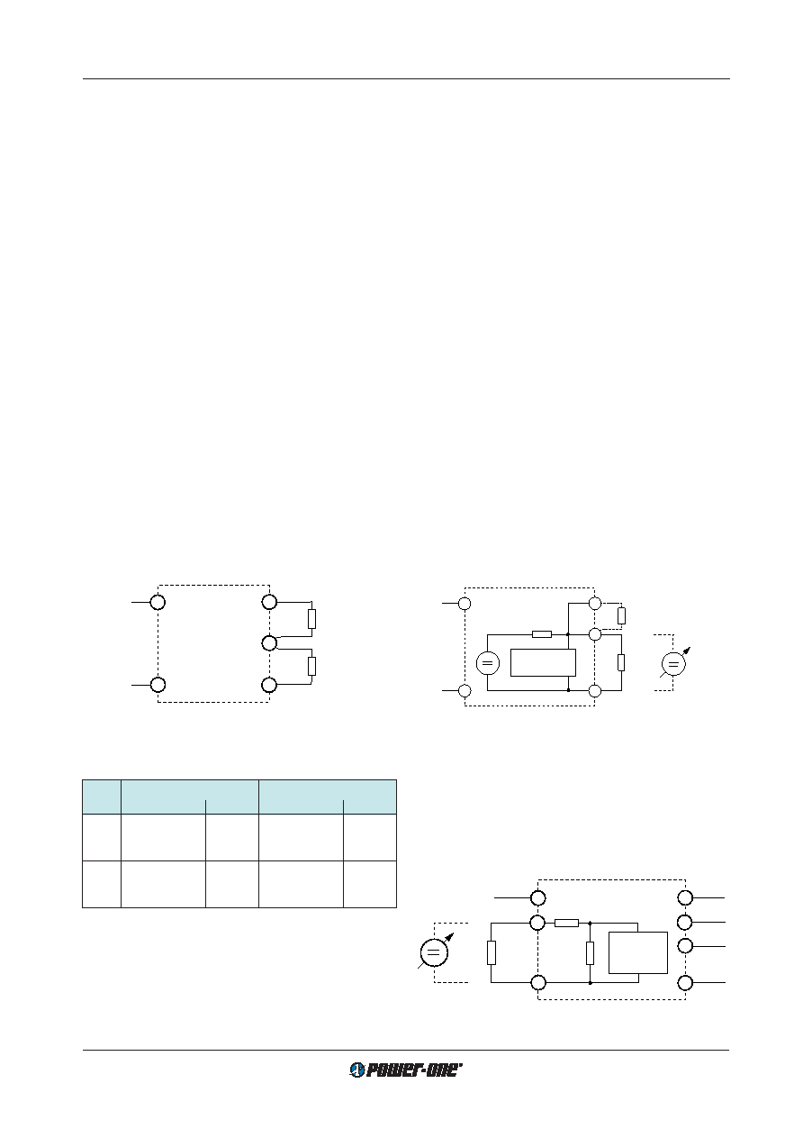
Fig. 22
Output voltage control for double output units by means of
the Trim input.
R
Vo+
Vo–
+
U
ext
–
4 k
Uref 2.5 V
control
circuit
Vi+
Vi–
R
ext1
R
ext 2
06029
Fig. 21
Output voltage control for single output units, -0503- types
and double output units fitted with option R by means of
the R input.
Single output units, -0503- types and double output units fit-
ted with option R:
The R input is referenced to the secondary side of the con-
verter. Adjustment of the output voltage is possible by
means of either an external resistor or a voltage source.
a) Adjustment by means of an external resistor
Rext.
Depending upon the value of the required output voltage,
the resistor shall be connected.
either: Between the R pin and Vo– to achieve an output
voltage adjustment range of approximately
Uo = 80...100 % Uo nom.
Uo
Rext1
≈ 4 k –––––––––
Uo nom – Uo
or: Between the R pin and Vo+ to achieve an output volt-
age range of approximately
Uo = 100...105 % Uo nom.
(
Uo – 2.5V)
Rext2 ≈ 4 k ––––––––––––––––––
2.5 V (
Uo/Uo nom – 1)
b) Adjustment by means of an external voltage
Uext be-
tween Vo– and R pins.
The control voltage range is 1.96...2.62 V and allows for
an adjustment in the range of approximately 80...105%
of
Uo nom.
Uo 2.5 V
Uext
≈ –––––––––
Uo nom
Attempting to adjust the output below this range will
cause the converter to shut down (hiccup mode).
Note: Applying an external control voltage >2.75 V may
damage the converter.
R
Vo+
Vo–
Vi+
Vi–
R
ext2
R
ext1
06131
Fig. 20
Output voltage control for single output units synchronous
rectification.
Table 8: Uo versus Uext approximate values
Uo nom
Typ. values of
Rext1
Typ. values of
Rext2
[V]
Uo [% of Uo nom] Rext1 [k] Uo [% of Uo nom] Rext2 [k]
3.3
90
0.47
100
∞
95
2.7
105
15
100
∞
110
6.8
5.1
90
3.3
100
∞
95
8.2
105
9.1
100
∞
110
3.9-
相關(guān)PDF資料 |
PDF描述 |
|---|---|
| 110IMY15-0503-9RIZ | 2-OUTPUT 12.6 W DC-DC REG PWR SUPPLY MODULE |
| 110IMY15-15-15-8RC | 2-OUTPUT 16.8 W DC-DC REG PWR SUPPLY MODULE |
| 110IMX35D12D12-8Z | 4-OUTPUT 35 W DC-DC REG PWR SUPPLY MODULE |
| 12A3.3S | 1-OUTPUT 1 W DC-DC UNREG PWR SUPPLY MODULE |
| 112076 | 1-OUTPUT AC-DC REG PWR SUPPLY MODULE |
相關(guān)代理商/技術(shù)參數(shù) |
參數(shù)描述 |
|---|---|
| 110IMY15-05-8RGZ | 功能描述:DC/DC CONVERT 5.1V 2.5A 制造商:bel power solutions 系列:* 零件狀態(tài):新產(chǎn)品 標(biāo)準(zhǔn)包裝:56 |
| 110IMY15-05-8RGZ-G | 功能描述:DC/DC CONVERT 5.1V 2.5A 制造商:bel power solutions 系列:* 零件狀態(tài):新產(chǎn)品 標(biāo)準(zhǔn)包裝:30 |
| 110IMY15-05-9R | 制造商:POWER-ONE 制造商全稱:Power-One 功能描述:15 Watt DC-DC Converters |
| 110IMY15-05-9RG | 制造商:POWER-ONE 制造商全稱:Power-One 功能描述:15 Watt DC-DC Converters |
| 110IMY15-12-12-8 | 功能描述:DC/DC轉(zhuǎn)換器 15W (2x 12V) DC Input (60-150V) RoHS:否 制造商:Murata 產(chǎn)品: 輸出功率: 輸入電壓范圍:3.6 V to 5.5 V 輸入電壓(標(biāo)稱): 輸出端數(shù)量:1 輸出電壓(通道 1):3.3 V 輸出電流(通道 1):600 mA 輸出電壓(通道 2): 輸出電流(通道 2): 安裝風(fēng)格:SMD/SMT 封裝 / 箱體尺寸: |
發(fā)布緊急采購,3分鐘左右您將得到回復(fù)。