- 您現(xiàn)在的位置:買賣IC網(wǎng) > PDF目錄384069 > 10A4-T3 (Won-Top Electronics Co., Ltd.) 10A STANDARD DIODE PDF資料下載
參數(shù)資料
| 型號: | 10A4-T3 |
| 廠商: | Won-Top Electronics Co., Ltd. |
| 英文描述: | 10A STANDARD DIODE |
| 中文描述: | 10A條標(biāo)準(zhǔn)二極管 |
| 文件頁數(shù): | 1/4頁 |
| 文件大小: | 57K |
| 代理商: | 10A4-T3 |
10A05 – 10A10
1 of 4 2006 Won-Top Electronics
Pb
10A05 – 10A10
10A STANDARD DIODE
Features
!
Diffused Junction
!
Low Forward Voltage Drop
!
High Current Capability A B A
!
High Reliability
!
High Surge Current Capability
Mechanical Data
C
!
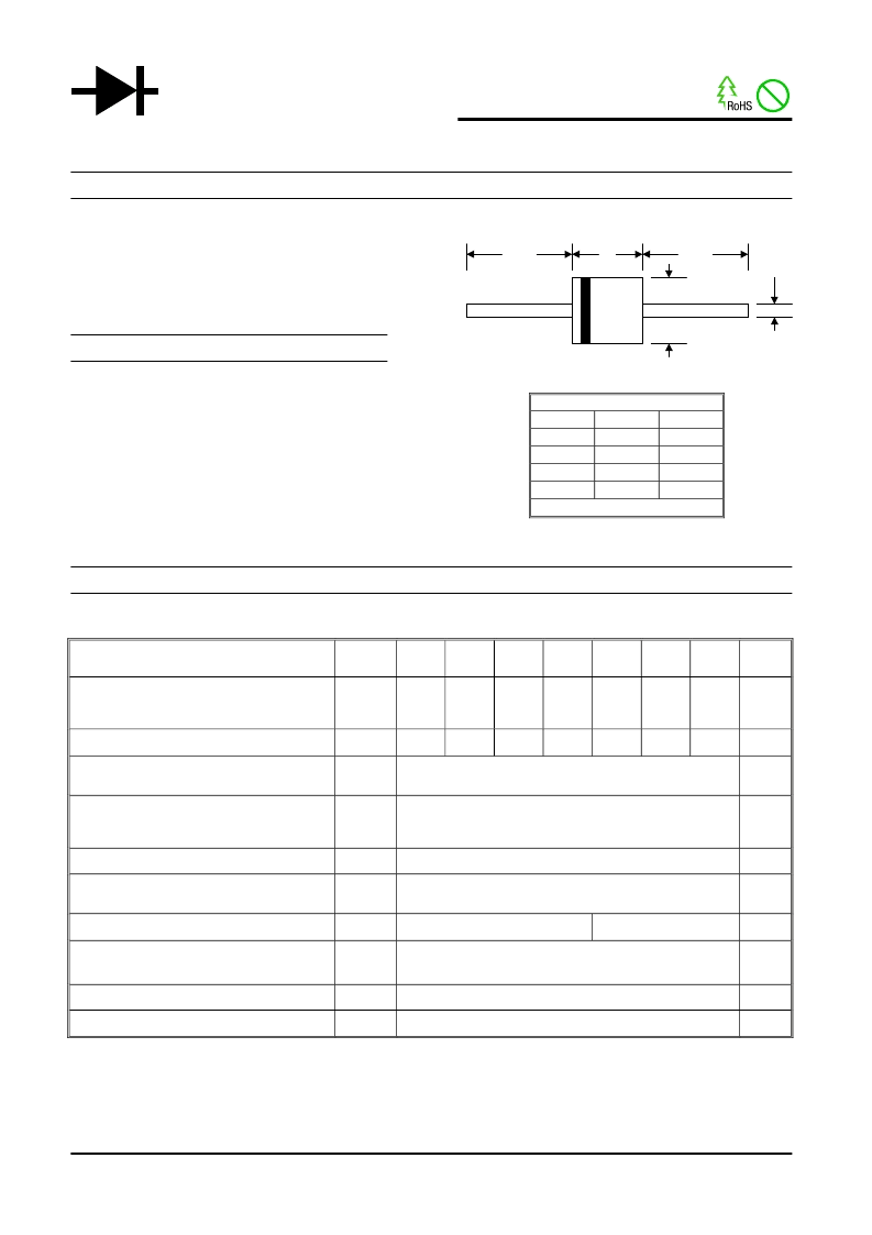
Case: P-600, Molded Plastic D
!
Terminals: Plated Leads Solderable per
MIL-STD-202, Method 208
!
Polarity: Cathode Band
!
Weight: 2.1 grams (approx.)
!
Mounting Position: Any
!
Marking: Type Number
!
Lead Free: For RoHS / Lead Free Version,
Add “-LF” Suffix to Part Number, See Page 4
Maximum Ratings and Electrical Characteristics
@T
A
=25°C unless otherwise specified
Single Phase, half wave, 60Hz, resistive or inductive load.
For capacitive load, derate current by 20%.
Characteristic
Symbol
10A05
10A1
10A2
10A4
10A6
10A8
10A10
Unit
Peak Repetitive Reverse Voltage
Working Peak Reverse Voltage
DC Blocking Voltage
V
RRM
V
RWM
V
R
50
100
200
400
600
800
1000
V
RMS Reverse Voltage
V
R(RMS)
35
70
140
280
420
560
700
V
Average Rectified Output Current
(Note 1) @T
A
= 50°C
I
O
10
A
Non-Repetitive Peak Forward Surge Current
8.3ms Single half sine-wave superimposed on
rated load (JEDEC Method)
I
FSM
600
A
Forward Voltage @I
F
= 10A
V
FM
1.0
V
Peak Reverse Current @T
= 25°C
At Rated DC Blocking Voltage @T
A
= 100°C
I
RM
10
100
μA
Typical Junction Capacitance (Note 2)
C
j
150
80
pF
Typical Thermal Resistance Junction to Ambient
(Note 1)
R
JA
10
°C/W
Operating Temperature Range
T
j
-50 to +150
°C
Storage Temperature Range
T
STG
-50 to +150
°C
Note: 1. Leads maintained at ambient temperature at a distance of 9.5mm from the case
2. Measured at 1.0 MHz and applied reverse voltage of 4.0V D.C.
WTE
POWER SEMICONDUCTORS
P-600
Min
25.4
8.60
1.20
8.60
Dim
A
B
C
D
Max
—
9.10
1.30
9.10
All Dimensions in mm
相關(guān)PDF資料 |
PDF描述 |
|---|---|
| 10A05-T3 | 10A STANDARD DIODE |
| 10A10-T3 | 10A STANDARD DIODE |
| 10A1-T3 | 10A STANDARD DIODE |
| 10A2-T3 | 10A STANDARD DIODE |
| 10A6-T3 | 10A STANDARD DIODE |
相關(guān)代理商/技術(shù)參數(shù) |
參數(shù)描述 |
|---|---|
| 10A510405 | 制造商:未知廠家 制造商全稱:未知廠家 功能描述:WINKELVERB SCHWENK 4MM M5 |
| 10A510418 | 制造商:未知廠家 制造商全稱:未知廠家 功能描述:WINKELVERB SCHWENK 4MM G0.125 |
| 10A5331/471G | 制造商:DAL 功能描述:DALE NXC2D |
| 10A5331471G | 制造商:DAL 功能描述:DALE NXC2D |
| 10A6 | 功能描述:整流器 Silicon Rectifier R6,10A,600V RoHS:否 制造商:Vishay Semiconductors 產(chǎn)品:Standard Recovery Rectifiers 配置: 反向電壓:100 V 正向電壓下降: 恢復(fù)時間:1.2 us 正向連續(xù)電流:2 A 最大浪涌電流:35 A 反向電流 IR:5 uA 安裝風(fēng)格:SMD/SMT 封裝 / 箱體:DO-221AC 封裝:Reel |
發(fā)布緊急采購,3分鐘左右您將得到回復(fù)。