- 您現(xiàn)在的位置:買賣IC網(wǎng) > PDF目錄6507 > 100800F00000G (Aavid Thermalloy)THERMAL GREASE PDF資料下載
參數(shù)資料
| 型號: | 100800F00000G |
| 廠商: | Aavid Thermalloy |
| 文件頁數(shù): | 13/116頁 |
| 文件大小: | 0K |
| 描述: | THERMAL GREASE |
| MSDS 材料安全數(shù)據(jù)表: | Ther-O-Link 1000 |
| 標(biāo)準(zhǔn)包裝: | 1 |
| 系列: | Therolink 1000 |
| 類型: | 硅合成物 |
| 尺寸/尺寸: | 8 盎司罐裝 |
| 其它名稱: | 000007 |
第1頁第2頁第3頁第4頁第5頁第6頁第7頁第8頁第9頁第10頁第11頁第12頁當(dāng)前第13頁第14頁第15頁第16頁第17頁第18頁第19頁第20頁第21頁第22頁第23頁第24頁第25頁第26頁第27頁第28頁第29頁第30頁第31頁第32頁第33頁第34頁第35頁第36頁第37頁第38頁第39頁第40頁第41頁第42頁第43頁第44頁第45頁第46頁第47頁第48頁第49頁第50頁第51頁第52頁第53頁第54頁第55頁第56頁第57頁第58頁第59頁第60頁第61頁第62頁第63頁第64頁第65頁第66頁第67頁第68頁第69頁第70頁第71頁第72頁第73頁第74頁第75頁第76頁第77頁第78頁第79頁第80頁第81頁第82頁第83頁第84頁第85頁第86頁第87頁第88頁第89頁第90頁第91頁第92頁第93頁第94頁第95頁第96頁第97頁第98頁第99頁第100頁第101頁第102頁第103頁第104頁第105頁第106頁第107頁第108頁第109頁第110頁第111頁第112頁第113頁第114頁第115頁第116頁
11
READING
A
T
HERMAL
PERFORMANCE
GR
APH
EUROPE
ASIA
Italy Tel: +39 051 764011 email: sales.it@aavid.com
United Kingdom Tel: +44 1793 401400 email: sales.uk@aavid.com
Singapore Tel: +65 6362 8388 email: sales@aavid.com.sg
Taiwan Tel: +886(2) 2698-9888 email: sales@aavid.com.tw
AMERICA
USA Tel: +1 (603) 224-9988 email: info@aavid.com
www.aavidthermalloy.com
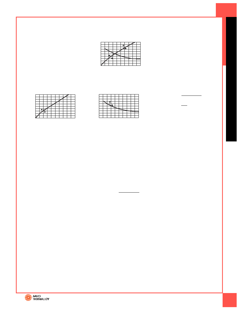
The performance graphs you will see in this
catalog (see graph 579802) are actually a
composite of two separate graphs which
have been combined to save space. The small
arrows on each curve indicate to which axis
the curve corresponds. Thermal graphs are
published assuming the device to be cooled
is properly mounted and the heat sink is in
its recommended mounting position.
GRAPH A is used to show heat sink perform-
ance when used in a natural convection envi-
ronment (i.e. without forced air). This graph
starts in the lower left hand corner with the
horizontal axis representing the heat dissipa-
tion (watts) and the vertical left hand axis
representing the rise in heat sink mounting
surface temperature above ambient (°C). By
knowing the power to be dissipated, the
temperature rise of the mounting surface
can be predicted. Thermal resistance in natu-
ral convection is determined by dividing this
temperature rise by the power input (°C/W).
EXAMPLE A: Aavid Thermalloy part number
579802 is to be used to dissipate 3 watts of
power in natural convection. Because we are
dealing with natural convection, we refer to
graph “A”. Knowing that 3 watts are to be dis-
sipated, follow the grid line to the curve and
find that at 3 watts there is a temperature
rise of 75°C. To get the thermal resistance,
divide the temperature rise by the power
dissipated, which yields 25°C/W.
GRAPH B is used to show heat sink per-
formance when used in a forced convec-
tion environment (i.e. with forced air flow
through the heat sink). This graph has its
origin in the top right hand corner with
the horizontal axis representing air velocity
over the heat sink LFM* and the vertical
axis representing the thermal resistance of
the heat sink (°C/W). Air velocity is calculat-
ed by dividing the output volumetric flow
rate of the fan by the cross-sectional area
of the outflow air passage.
EXAMPLE B: For the same application
we add a fan which blows air over the heat
sink at a velocity of 400 LFM.
The addition of a fan indicates the use of
forced convection and therefore we refer
to graph “B”. This resistance of 9.50°C/W is
then multiplied by the power to be dissi-
pated, 3 watts. This yields a temperature
rise of 28.5°C.
CONVERTING VOLUME
TO VELOCITY
Although most fans are normally rated and
compared at their free air delivery at zero
back pressure, this is rarely the case in most
applications. For accuracy, the volume of
output must be derated 60%–80% for
the anticipation of back pressure.
EXAMPLE: The output air volume
of a fan is given as 80 CFM. The output area
is 6 inches by 6 inches or 36 in2 or 25 ft2.
To find velocity:
80
0.25
Velocity is 320 LFM, which at 80%,
derates to 256 LFM.
DESIGN ASSISTANCE
Aavid Thermalloy can assist in the design
of heat sinks for both forced and natural
convection applications. Contact us for help
with your next thermal challenge. For more
information, visit our web site at:
www.aavidthermalloy.com
Heat Dissipated—Watts
0
20
40
60
80
100
01
2
3
4
5
Mounting
Surface
Temp
Rise
Above
Ambient—
°
C
Air Velocity—Feet Per Minute
Thermal
Resistance
From
MTG
Surface
to
Ambient—
°
C/Watt
20
16
12
4
8
0
400
200
600
800
1000
GRAPH B
Velocity (LFM) =
Velocity =
= 320
Air Velocity—Feet Per Minute
Heat Dissipated—Watts
Thermal
Resistance
From
MTG
Surface
to
Ambient—
°
C/Watt
20
0
20
40
60
80
100
01
2
3
4
5
16
12
4
8
0
400
200
600
800
1000
Mounting
Surface
Temp
Rise
Above
Ambient—
°
C
GRAPH A
579802
Reading a Thermal Performance Graph
Velocity
(LFM)* = Volume (CFM)**
area (ft2)
* Linear feet per minute
** Cubic feet per minute
Volume (CFM)
area (ft2)
相關(guān)PDF資料 |
PDF描述 |
|---|---|
| CSKO886 | BOX STEEL 8X8X6" GREY |
| CS886 | BOX STEEL 8X8X6" GREY |
| 1590EGY | BOX ALUM 7.40X4.72X3.30" GREY |
| 1590EBK | BOX ALUM 7.40X4.72X3.30" BLACK |
| PC123FY8J00F | PHOTOCOUPLER TRAN OUT WIDE 4-DIP |
相關(guān)代理商/技術(shù)參數(shù) |
參數(shù)描述 |
|---|---|
| 100800NP | 制造商:LAPP/CONTACT CONNECTORS 功能描述:HBE 16 TOP ENTRY HOOD WITH DOUBLE LEVER BOLTS, 3/4IN NPT |
| 100-801 | 制造商:TE Connectivity 功能描述:CURRENT TRANSFORMER; Input Current:800A; Turns Ratio:800:5; Frequency Min:50Hz; Frequency Max:400Hz; Secondary Burden Resistance:0.266ohm; Transformer Mounting:Panel; Current Ratio:800:5 A; Frequency Range:50Hz to 400Hz; Series:100 ;RoHS Compliant: NA |
| 1008-018J | 功能描述:固定電感器 .0018uH 5% .05ohm Unsheilded SMT RF RoHS:否 制造商:AVX 電感:10 uH 容差:20 % 最大直流電流:1 A 最大直流電阻:0.075 Ohms 工作溫度范圍:- 40 C to + 85 C 自諧振頻率:38 MHz Q 最小值:40 尺寸:4.45 mm W x 6.6 mm L x 2.92 mm H 屏蔽:Shielded 端接類型:SMD/SMT 封裝 / 箱體:6.6 mm x 4.45 mm |
| 1008-018J TR 2000 | 制造商:API Delevan 功能描述:INDUCTOR .0018 UH UNSHIELDED SMD |
| 1008-018K | 功能描述:固定電感器 .0018uH 10% .05ohm Unsheilded SMT RF RoHS:否 制造商:AVX 電感:10 uH 容差:20 % 最大直流電流:1 A 最大直流電阻:0.075 Ohms 工作溫度范圍:- 40 C to + 85 C 自諧振頻率:38 MHz Q 最小值:40 尺寸:4.45 mm W x 6.6 mm L x 2.92 mm H 屏蔽:Shielded 端接類型:SMD/SMT 封裝 / 箱體:6.6 mm x 4.45 mm |
發(fā)布緊急采購,3分鐘左右您將得到回復(fù)。