- 您現(xiàn)在的位置:買賣IC網(wǎng) > PDF目錄366059 > 1-1414704-0 (Tyco Electronics) Automotive Relays PDF資料下載
參數(shù)資料
| 型號: | 1-1414704-0 |
| 廠商: | Tyco Electronics |
| 元件分類: | 特殊繼電器 |
| 英文描述: | Automotive Relays |
| 中文描述: | 汽車繼電器 |
| 文件頁數(shù): | 2/3頁 |
| 文件大小: | 1294K |
| 代理商: | 1-1414704-0 |
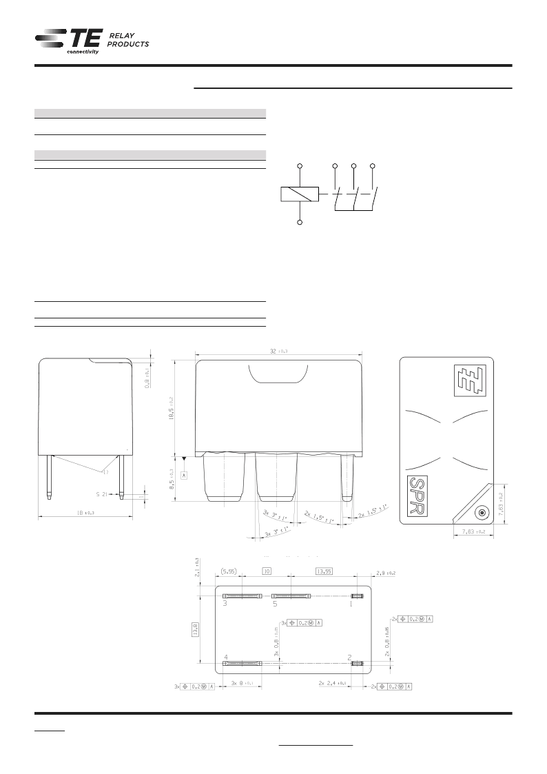
Star Point Relay SPR
(Continued)
10-2012, Rev. 1012
www.te.com
2011 Tyco Electronics Corporation,
a TE Connectivity Ltd. company.
Datasheets and product specification ac-
cording to IEC 61810-1 and to be used only
together with the ‘Definitions’ section.
Datasheets and product data is subject to the
terms of the disclaimer and all chapters of
the ‘Definitions’ section, available at
http://relays.te.com/definitions
Datasheets, product data, ‘Definitions’ sec-
tion, application notes and all specifications
are subject to change.
2
Automotive Relays
High Current Devices
Insulation Data
Initial dielectric strength
between contact and coil
500VAC
rms
Other Data
EU RoHS/ELV compliance
Ambient temperature
Cold storage, IEC 60068-2-1
Dry heat, IEC 60068-2-2
Temperature cycling (shock),
IEC 60068-2-14, Na
Damp heat cyclic,
IEC 60068-2-30, Db, Variant 1
Flowing mixed gas corrosion test,
IEC 60068-2-60, Ke, method 1
Degree of protection
Vibration resistance (functional),
IEC 60068-2-64 (random) energized
IEC 60068-2-64 (random) not energized 20 to 1000Hz >4g ms
Shock resistance (functional),
IEC 60068-2-27 (half sine) 6ms, energized
IEC 60068-2-27 (half sine) 6ms, not energized
Mounting
Weight
Packaging unit
compliant
-40°C to 125°C
2000h; -40°C
500h; +135°C
500 cycles; -40/+135°C
83 cycles (2000h) 25°C/55°C/93%RH
IP67 (IEC 60529), RT III (IEC 61810)
10 days
20 to 1000Hz >6g ms
>40g
>10g
welding process on leadframe
approx. 30g (1.06oz)
357 pcs.
1 form 3, 3 NO
Terminal Assignment
3
5
4
1
2
Dimensions
View of the terminals
Bottom view
1) Epoxy at terminals exceeds max. 0.9mm over
coverage.
2) Permanent acceptable deformation 0.25mm
respectively 0.5mm temporarily.
Maximum permissible thermal load of the
terminals during the resistance welding process
depends on leadframe design.
相關PDF資料 |
PDF描述 |
|---|---|
| 1-1414705-0 | Automotive Relays |
| 1-1414939-4 | Automotive Relays |
| 7-1414778-3 | Automotive Relays |
| 1-1423696-5 | Thermal Circuit Breakers |
| 1-1423696-6 | Thermal Circuit Breakers |
相關代理商/技術參數(shù) |
參數(shù)描述 |
|---|---|
| 1-1414705-0 | 制造商:TE Connectivity 功能描述:V23135W1002A309-EV-CBOX 制造商:TE CONNECTIVITY P&B 功能描述:V23135W1002A309-EV-CBOX |
| 1-1414728-0 | 制造商:TE Connectivity 功能描述: |
| 1-1414729-0 | 制造商:TE Connectivity 功能描述: |
| 1-1414732-0 | 制造商:TE Connectivity 功能描述:V23132A2001X026 - Bulk 制造商:TE CONNECTIVITY P&B 功能描述:V23132A2001X026 |
| 1-1414760-0 | 功能描述:通用繼電器 V23086C1021A502-EV-USBX RoHS:否 制造商:Omron Electronics 觸點形式:1 Form A (SPST-NO) 觸點電流額定值:150 A 線圈電壓:24 VDC 線圈電阻:144 Ohms 線圈電流:167 mA 切換電壓:400 V 安裝風格:Chassis 觸點材料: |
發(fā)布緊急采購,3分鐘左右您將得到回復。